WIKA TW45 threaded protection tube to DIN 43772 forms 5 and 8
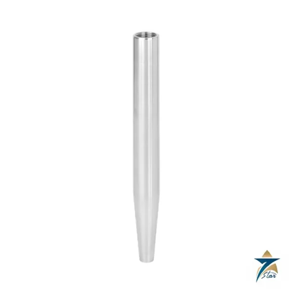
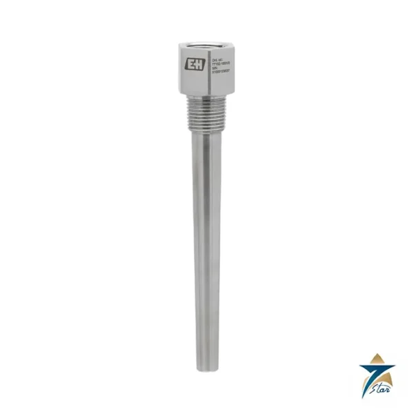
The WIKA TW45 is a threaded protection tube made from stainless steel 1.4571 for low and medium process loads. It is designed after DIN 43772 and is used in the chemical industry, process technology and equipment manufacturing. A protection tube differs from a bar-stock thermowell in how it is made: the TW45 is built from a tube closed at the tip by a welded solid end, which makes it lighter and quicker to respond, but less suited to heavy flow loads than the TW20 or TW25. Seven Star LLC supplies the TW45 in Oman and the GCC as an independent supplier in Muscat.
Decoding the TW45 forms
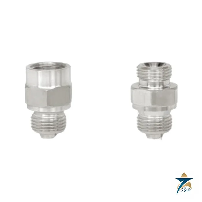
Two designs are listed. TW45-F is form 5 per DIN 43772: a process thread G ½ B or G ¾ B male, and a female thread for the thermometer (G ½ or G ¾). TW45-G is form 8: the same process thread, but the connection to the thermometer is itself a G ½ B or G ¾ B male thread, which suits machine glass thermometers and certain dial thermometers. The version is either per DIN 43772 or a design similar to DIN 43772 with a thinner wall for fast response.
Technical specifications of the TW45
| Parameter |
Specification |
| Manufacturer / part number |
WIKA / TW45 |
| Type |
Threaded protection tube |
| Forms |
TW45-F form 5; TW45-G form 8 |
| Version |
Per DIN 43772, or similar to DIN 43772 (fast response) |
| Wetted material |
Stainless steel 1.4571 |
| Process connection |
G ½ B or G ¾ B male thread |
| Connection to thermometer, TW45-F |
G ½ or G ¾ female thread |
| Connection to thermometer, TW45-G |
G ½ B or G ¾ B male thread |
| Bore, per DIN 43772 |
7, 9 or 11 mm |
| Bore, similar to DIN 43772 |
6.2, 8.2, 8.5 or 10.2 mm |
| Insertion length U, TW45-F |
82, 142, 182, 232 or 382 mm |
| Insertion length U, TW45-G |
73, 110, 170, 260 or 410 mm |
| Overall length L |
Insertion length U1 + 28 mm |
| Certificates (option) |
2.2 test report; 3.1 inspection certificate |
Dimensional examples from the data sheet
The dimension table covers every bore, thread and wall combination. Some examples for TW45-F in stainless steel 1.4571 illustrate how wall thickness changes with the bore.
| Process thread |
Bore Ø d1 |
Outer Ø F1 |
Wall S |
Weight, U1 = 82 mm |
Weight, U1 = 382 mm |
| G ½ B |
7 mm |
12 mm |
2.5 mm |
0.15 kg |
0.33 kg |
| G ½ B |
11 mm |
14 mm |
1.5 mm |
0.12 kg |
0.28 kg |
| G ½ B |
6.2 mm |
8 mm |
0.9 mm |
0.12 kg |
0.18 kg |
| G ¾ B |
9 mm |
14 mm |
2.5 mm |
0.24 kg |
0.45 kg |
| G ¾ B |
10.2 mm |
12 mm |
0.9 mm |
0.21 kg |
0.28 kg |
The sealing collar is 26 mm in diameter on G ½ B and 32 mm on G ¾ B, with spanner widths of 27 and 32 mm respectively. A copper-alloy variant with an 8.5 mm bore also appears in the table for the fast-response design.
Working principle and limits of the TW45
The protection tube isolates the thermometer from the medium, so the thermometer can be exchanged while the line is in operation and is shielded from pressure and flow. The permitted process temperature and pressure are not stated as one value: they depend on the DIN 43772 load diagram, the tube dimensions and material, and the flow rate and density of the medium. A thin-walled fast-response tube will tolerate less load than a thick-walled one, so the version must be matched to the duty. An optional wake frequency calculation per Dittrich/Klotter is provided as an engineered service by the manufacturer and is subject to charges.
Matching thermometers to the TW45
Stem lengths follow formulas in the data sheet. For TW45-F with a dial thermometer on connection designs S, 4, 4.1, 5, 6.1, 6.2, 6.3 and 7, l1 = L − 10 mm for a parallel thread, or l1 = U1 + 18 mm; with a tapered thread, l1 = L − 2 mm. For TW45-G with connection design 3, l1 = L − 12 mm. Machine glass thermometers use similar rules with connection designs E and 3. These relationships make it straightforward to specify a thermometer stem to suit the chosen tube.
Related models: TW15, TW20 and TW61
If the process load is higher than a tube can handle, the threaded bar-stock TW15 or the weld-in TW20 and TW25 are the next step. If the process is sanitary, the TW61 orbital-weld tube is intended for that duty. The TW45 remains the economical, standard-pattern choice for general utility and chemical lines.
Selection and ordering checklist for the TW45
- Form: TW45-F (form 5) or TW45-G (form 8).
- Version: per DIN 43772 or fast-response design.
- Process thread G ½ B or G ¾ B and the thermometer thread.
- Bore size and the thermometer sheath that must fit it.
- Insertion length U from the standard list.
- Certificate level 2.2 or 3.1.
- Process data to confirm the load class.
Installation and maintenance of the TW45
Use a suitable gasket on the sealing collar, tighten with the correct spanner width, and avoid over-torquing a thin-walled tube. Inspect the tube at shutdowns for corrosion, and handle thin-walled fast-response designs carefully because their wall is under 1 mm in some sizes.
Typical applications in Oman and the GCC
Utility water, chemical dosing, HVAC plant, process skids and general processing lines in the region are typical uses, particularly where the process loads are moderate and installation by a simple thread is preferred.
Information to send with an RFQ for the TW45
- Form, version and process thread.
- Bore and insertion length.
- Thermometer model and thread to fit.
- Medium, temperature, pressure and flow.
- Certificates, quantity and delivery location.
Documents and quotation
The WIKA data sheet TW 95.45 for the TW45 is attached on this page. Send the details above and Seven Star LLC will quote as an independent supplier, with no claim to an official WIKA status.





Reviews
There are no reviews yet.