WIKA TW25 weld-in thermowell with variable welding diameter
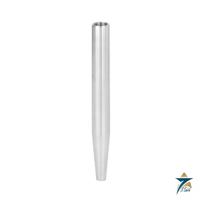
The WIKA TW25 is a weld-in thermowell machined from solid bar stock for high process loads. Where the TW20 is made for fixed, standardised welding sockets, the TW25 is defined by a bar diameter that the customer chooses, from 25.4 to 49.5 mm (1 to 1.95 in). That freedom is the reason to specify a TW25: the thermowell can be matched to an existing nozzle, a customer drawing or a special piping class instead of a catalogue socket. Seven Star LLC supplies the TW25 in Oman and the GCC as an independent supplier in Muscat, and this page sets out the options so your RFQ can be quoted without delay.
TW25 forms and what the designation tells you
The data sheet describes three thermowell designs: TW25-A is tapered, TW25-B is straight and TW25-C is stepped. The tapered design is stiffer at the root and slimmer at the tip, which gives a fast response and a higher natural frequency; the straight design is the simplest geometry; the stepped design combines a heavy root section with a narrower tip. The connection to the thermometer is a ½ NPT or G ½ female thread, and the bore is Ø 6.6 mm or Ø 8.5 mm.
Technical specifications of the TW25
| Parameter |
Specification |
| Manufacturer / part number |
WIKA / TW25 |
| Type |
Weld-in thermowell from solid bar stock |
| Forms |
TW25-A tapered; TW25-B straight; TW25-C stepped |
| Wetted materials |
Stainless steel 316/316L, 304/304L, 1.4571, carbon steel A105; special materials on request |
| Welding (bar) diameter |
Customer specified, 25.4 … 49.5 mm (1 … 1.95 in) |
| Connection to thermometer |
½ NPT female or G ½ female; other threads on request |
| Bore size |
Ø 6.6 mm or Ø 8.5 mm |
| Insertion length U |
100 to 400 mm in 50 mm steps, or 6, 7, 10, 13, 16 in; others on request |
| Maximum insertion length |
800 mm (31.5 in); up to 1575 mm (62 in) on request |
| Connection length H |
45 mm (1.75 in) standard; maximum 250 mm (10 in) |
| Tip thickness |
6.4 mm (0.25 in); others on request |
| Certificates (option) |
2.2 test report; 3.1 inspection certificate |
| Wake frequency calculation (option) |
Per ASME PTC 19.3 TW-2016 |
Reference dimensions of the tapered TW25-A
The data sheet tabulates three example bar diameters. In these examples the root diameter equals the welding diameter and the tip diameter stays at 19 mm (0.750 in).
| Welding Ø P |
Root Ø Q |
Tip Ø V |
Weight, U = 100 mm |
Weight, U = 560 mm |
| 25.4 mm (1.000 in) |
25.4 mm |
19 mm |
0.4 kg (0.881 lbs) |
1.5 kg (3.306 lbs) |
| 35.0 mm (1.380 in) |
35.0 mm |
19 mm |
0.7 kg (1.543 lbs) |
2.8 kg (6.172 lbs) |
| 49.5 mm (1.945 in) |
49.5 mm |
19 mm |
1.4 kg (3.086 lbs) |
4.9 kg (10.802 lbs) |
These are reference values for H = 45 mm. Because the TW25 bar diameter is free within the range, intermediate sizes are possible and the final drawing is confirmed per order.
Operating limits and the wake frequency check for the TW25
WIKA does not publish a single maximum temperature or pressure for the TW25. The limits depend on the thermowell design, its dimensions and material, and on the process conditions, namely flow rate and medium density. The optional wake frequency calculation per ASME PTC 19.3 TW-2016 evaluates the risk of vortex-induced vibration and the static loads from lateral flow and process pressure over temperature. It can be carried out independently with an online tool or as an engineered service by the manufacturer, which is subject to charges. When you request a quotation, give us the operating data so that the calculation can be requested with the thermowell, because it often decides between a tapered, straight or stepped form and the length.
Fitting a thermometer into the TW25
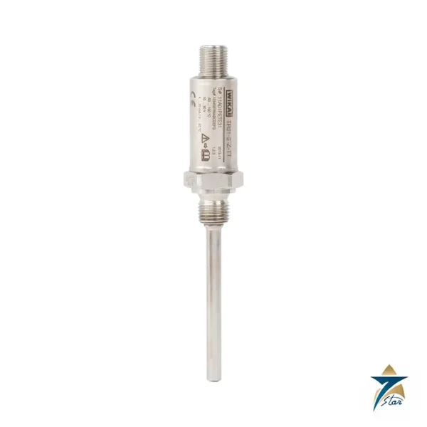
The stem length of a dial thermometer must fit the thermowell. For connection designs S, 4, 4.1, 5, 6.1, 6.2, 6.3 and 7, the data sheet gives l1 = U + H − 10 mm with a parallel thread and l1 = U + H − 2 mm with a tapered thread; for connection design 2 the formula is l1 = U + H − 30 mm. These apply to the standard 6.4 mm tip thickness. Electrical thermometers such as resistance thermometers are sized from the same insertion length and bore. The manufacturer states that the TW25 suits numerous electrical and mechanical WIKA thermometers.
Related thermowells: TW20, TW10, TW15 and TW45
Choose the TW25 over the TW20 when the weld-in nozzle is non-standard, or when a bar diameter between the three TW20 sizes is needed. The flanged TW10 and the threaded TW15 are alternatives when the plant standard is a flange or a thread rather than a weld. The threaded protection tube TW45 follows DIN 43772 and is intended for lighter process loads. Selecting between them is mostly a question of connection type and loading rather than of the thermometer.
Selection and ordering checklist for the TW25
- Bar (welding) diameter between 25.4 and 49.5 mm.
- Form: tapered, straight or stepped, with root and tip diameters if specified.
- Insertion length U and connection length H.
- Thermometer thread (½ NPT or G ½) and bore size.
- Wetted material and certificate level.
- Whether to supply with an assembled thermometer.
- Process temperature, pressure, flow velocity and medium for a wake frequency calculation.
Installation and maintenance of the TW25
Because the TW25 is weld-in, the welding detail and any post-weld inspection are decided by the project piping specification. Confirm the weld preparation against the bar diameter on the drawing, keep the bore and thread clean during welding, and fit the thermometer so that its tip touches the bottom of the bore for a good thermal contact. In service, the thermometer can be removed without opening the process. Review the thermowell at planned shutdowns for erosion and cracking, particularly where flow velocities are high.
Typical applications in Oman and the GCC
The manufacturer lists the petrochemical industry, on-shore and off-shore plant and plant construction. Around the Gulf that translates to hydrocarbon processing trains, power plants, desalination and utilities lines where weld-in thermowells are preferred because they remove a potential leak path. The TW25 is helpful on equipment where the nozzle size is dictated by the vessel vendor.
Information to send with an RFQ for the TW25
- Bar diameter, form and lengths U and H.
- Material and certificates.
- Thermometer thread and bore.
- Operating conditions for a wake frequency calculation.
- Quantity, project and delivery location.
Documents and quotation
The WIKA data sheet TW 95.25 for the TW25 is attached on this page. Please send your specification and Seven Star LLC will return a quotation as an independent supplier, without any claim to an official WIKA role.










Reviews
There are no reviews yet.