H3CR-AP: 11-pin multi-mode timer for voltage-type control signals
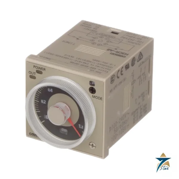
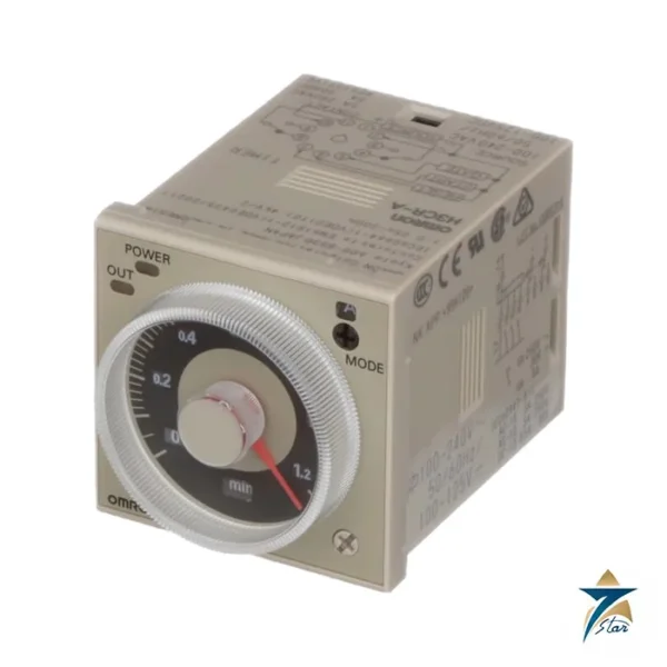
The Omron H3CR-AP is the voltage-input version of the 11-pin H3CR-A multifunctional timer. Its start, reset and gate terminals respond to an applied voltage rather than to a contact closure, which suits signals coming from PNP sensors, PLC outputs or other powered sources. Seven Star LLC supplies the H3CR-AP in Oman and the GCC as an independent supplier in Muscat. Read on for the decoded part number and the selection points that matter.
- H3CR-A is the multifunctional timer type with eight selectable operating modes.
- No pin number after A means the 11-pin form.
- P means voltage input (PNP type); without P the input is no-voltage (NPN).
- No further letter means a DPDT relay output.
- Supply voltage is added when ordering: 100-240AC/100-125DC or 24-48AC/12-48DC.
The voltage input removes the need for an interposing relay when a PLC output or 24 V sensor is the trigger, which is why the H3CR-AP is often specified in control panels that are already built around solid-state signals.
H3CR-AP technical specifications
| Parameter |
Specification |
| Manufacturer / part number |
Omron H3CR-AP |
| Pin type / mounting |
11-pin plug-in |
| Time range |
0.05 s to 300 h |
| Operating modes |
A, B, B2, C, D, E, G and J |
| Input type |
Voltage input (PNP) |
| Input levels, 100-240 V version |
High 85 to 264 VAC / 85 to 137.5 VDC; low 0 to 10 VAC/VDC |
| Input levels, 24-48 V version |
High 20.4 to 52.8 VAC / 10.8 to 52.8 VDC; low 0 to 2.4 VAC / 0 to 1.2 VDC |
| Max. capacitance between input lines |
1,200 pF (terminals 6 and 7) |
| Output |
DPDT relay |
| Power consumption, 100-240 V version |
Relay ON approx. 2.5 VA (2.2 W); relay OFF approx. 1.8 VA (1.7 W) at 240 VAC, 60 Hz |
| Power consumption, 24-48 V version |
Relay ON approx. 0.9 W; relay OFF approx. 0.3 W at 24 VDC |
| Rated supply voltage |
100 to 240 VAC (50/60 Hz) / 100 to 125 VDC, or 24 to 48 VAC (50/60 Hz) / 12 to 48 VDC |
| Operating voltage range |
85% to 110% of rated supply voltage (90% to 110% at 12 VDC) |
| Contact rating |
5 A at 250 VAC / 30 VDC, resistive; minimum load 10 mA at 5 VDC |
| Operating time accuracy |
±0.2% FS max. |
| Setting error |
±5% FS ±50 ms |
| Influence of temperature |
±1% FS max. |
| Insulation / dielectric |
100 MΩ min. at 500 VDC / 2,000 VAC for 1 min |
| Ambient temperature |
Operating −10 to 55°C, no icing; storage −25 to 65°C |
| Operating humidity |
35% to 85% |
| Life |
Mechanical 20 million operations min.; electrical 100,000 operations min. at 5 A, 250 VAC resistive |
| Mounting |
DIN track, surface and flush mounting |
| Protection |
IP40 (panel surface) |
The power consumption figures for H3CR-AP include the consumption of the input circuit when terminals 2 and 7 and terminals 10 and 6 are short-circuited. Dielectric strength between input, control output and operating circuit is 2,000 VAC for this model, and the datasheet notes a setting error of +100 ms to 0 when the C, D or G signal turns off.
How H3CR-AP handles timing
The H3CR-AP times in the same way as the H3CR-A, but its input stage is an isolated voltage detector. A level inside the high band starts or gates the timer and a level inside the low band releases it. The high and low bands depend on the supply version, so a 24 V sensor can be used with a low-voltage timer or a mains-level signal with the 100 to 240 V version.
Eight modes are supported. Signal modes C, D and G time from the input edges while power stays on; power-start modes A, B, B2, E and J run from supply application. The wide AC/DC input span is helpful where both signal types exist in one plant.
| Full-scale value |
s |
x10 s |
min |
x10 min |
h |
x10 h |
| 1.2 |
0.05 to 1.2 |
1.2 to 12 |
0.12 to 1.2 |
1.2 to 12 |
0.12 to 1.2 |
1.2 to 12 |
| 3 |
0.3 to 3 |
3 to 30 |
0.3 to 3 |
3 to 30 |
0.3 to 3 |
3 to 30 |
| 12 |
1.2 to 12 |
12 to 120 |
1.2 to 12 |
12 to 120 |
1.2 to 12 |
12 to 120 |
| 30 |
3 to 30 |
30 to 300 |
3 to 30 |
30 to 300 |
3 to 30 |
30 to 300 |
The time unit and full-scale knobs combine to give 24 ranges on standard 0.05 s to 300 h models. Turning the set value below zero until the stop makes the output act instantly, which is a quick way to check wiring and sequence without waiting for a long time range to run out.
Sockets, accessories and related timers for H3CR-AP
H3CR-AP replaces the no-voltage H3CR-A when the control source changes from contacts to voltages, and the socket and cut-out stay the same. The transistor-output H3CR-AS is a different branch of the family. Sockets for the 11-pin form are listed below, and the unit can share an enclosure with 8-pin siblings if different sockets are used.
| Pins |
Mounting |
Socket models |
| 8-pin |
Front connecting, DIN track |
P2CF-08, P2CF-08-E (finger-safe), PF085A |
| 8-pin |
Back connecting |
P3G-08 (screw), PL08 (solder), PL08-Q (wrapping), PLE08-0 (PCB) |
| 11-pin |
Front connecting, DIN track |
P2CF-11, P2CF-11-E (finger-safe) |
| 11-pin |
Back connecting |
P3GA-11 (screw), PL11 (solder), PL11-Q (wrapping), PLE11-0 (PCB) |
Accessories listed for the family include the Y92F-30, Y92F-73 and Y92F-74 flush-mounting adapters, the Y92A-48B protective cover, Y92H-7 and Y92H-8 hold-down clips, Y92S-27 and Y92S-28 setting rings, Y92P-48GL and Y92P-48GB panel covers, and the Y92A-48G terminal cover for back-connecting screw sockets. The protective cover and flush adapters cannot be combined with the panel cover, so settle the front-panel arrangement before ordering.
Selection and ordering checklist for H3CR-AP
Use this list before you send an enquiry for H3CR-AP. Omron orders timers by model plus supply voltage, so the voltage is part of the order and cannot be added later.
- Confirm the signal type: voltage level, AC or DC, and the voltage value, so the correct supply band is chosen.
- Make sure the signal source can drive the 1,200 pF maximum input-line capacitance without false triggering.
- Decide the mode set needed from the eight available.
- Pick time range and whether the double-scale -301 style is available for your combination.
- Check relay loading and select the 11-pin socket.
- Be aware of inrush on 24 to 48 VAC/12 to 48 VDC supplies when the timer is switched by a non-contact device.
Installation, commissioning and maintenance of H3CR-AP
Connect the supply and input terminals according to the datasheet drawing, taking care to use the right pair of terminals for the voltage input. Voltage sources must be within the stated high and low bands to guarantee start and reset.
- Measure the actual signal level on the panel before wiring; marginal levels cause intermittent timing.
- Avoid long parallel signal cable runs that add capacitance on the input lines.
- Check for leakage from 2-wire sensors, which can hold the input in an undefined range.
- Test each mode with the zero-set function, then set final times.
- Document the voltage version on the panel label for maintenance.
Typical H3CR-AP applications in Oman and the GCC
Applications for the H3CR-AP are found where PLC outputs hand off timing to a dedicated hardware timer: heat-trace and heater soft-start sequences, delayed stop of lube-oil pumps after a motor trips, and timed purge before burner ignition. Because the input is a voltage, sequence signals from remote I/O can reach the timer without relays.
Industrial plants in the Gulf commonly mix 24 VDC control with mains-level interlock signals. The H3CR-AP wide input ranges let a single stocked version serve both, which reduces spare-part variety for maintenance teams.
H3CR family compared with H3CR-AP
The table places H3CR-AP next to the other timers in the same H3CR catalogue so you can confirm that you are asking for the right base model before the voltage is added.
| Model |
Pins |
Function |
Output |
Key difference |
| H3CR-A8 |
8 |
Multi-mode: A, B, B2, E, J (power start) |
DPDT relay |
Compact socket, five modes, no external input |
| H3CR-A |
11 |
Multi-mode: A, B, B2, C, D, E, G, J |
DPDT relay |
No-voltage (NPN) start, reset and gate input |
| H3CR-AP |
11 |
Same eight modes as H3CR-A |
DPDT relay |
Voltage (PNP) input for PLC or sensor signals |
| H3CR-A8E |
8 |
Time-limit plus instantaneous output |
SPDT + SPDT relay |
Instantaneous contact follows power |
| H3CR-AS / H3CR-A8S |
11 / 8 |
As H3CR-A / H3CR-A8 |
Transistor (NPN/PNP) |
Solid-state output, 24-48 VAC/12-48 VDC only |
| H3CR-F8 / F8N |
8 |
Twin timer, OFF-start / ON-start |
DPDT relay |
Separate ON and OFF time settings |
| H3CR-FN |
11 |
Twin timer, flicker ON start |
DPDT relay |
11-pin form of the ON-start twin timer |
Information to send with an RFQ for H3CR-AP
- Part number H3CR-AP, voltage band and quantity.
- Control signal voltage and type, AC or DC.
- Mode needed and time range.
- Load on the DPDT contact.
- Socket type and quantity.
- Delivery location.
Documents and quotation
A datasheet for the H3CR series is attached on this page, covering the model legend, time ranges, ratings, timing charts, dimensions and safety precautions for H3CR-AP and its siblings. Please read the precautions section before wiring.
Seven Star LLC is an independent supplier in Muscat and is not affiliated with the manufacturer. Send the part number H3CR-AP, the supply voltage and the quantity, and we will confirm availability and lead time for Oman and the GCC.
Other Models in the Omron H3cr Timers Range
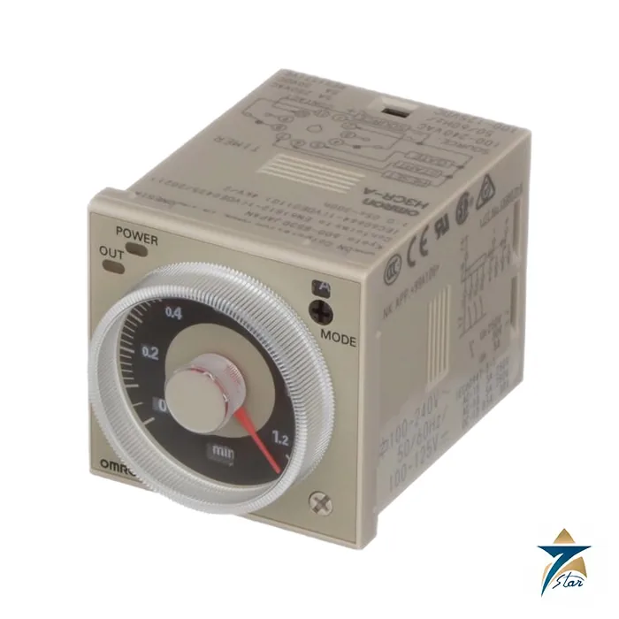
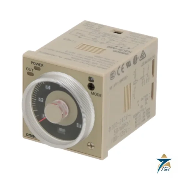
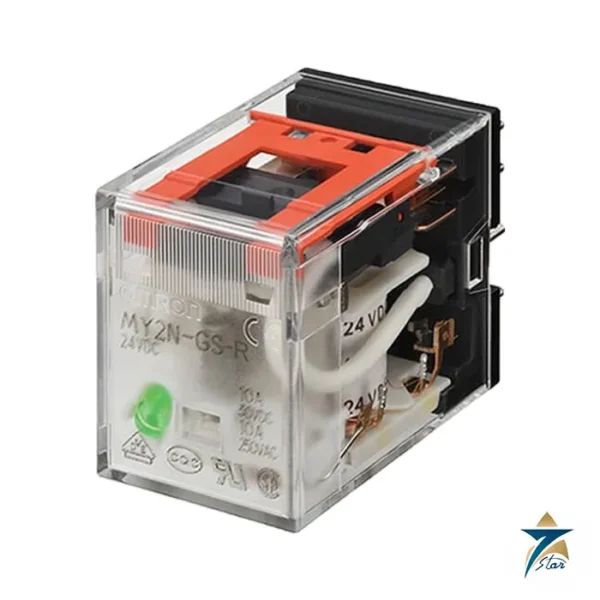
Seven Star LLC supplies models from the Omron H3cr Timers range in Oman and the GCC. Compare the related models below and request a quote for the one that matches your application.














Reviews
There are no reviews yet.