Endress+Hauser t-mass I 300 insertion thermal mass flowmeter for pipes and ducts
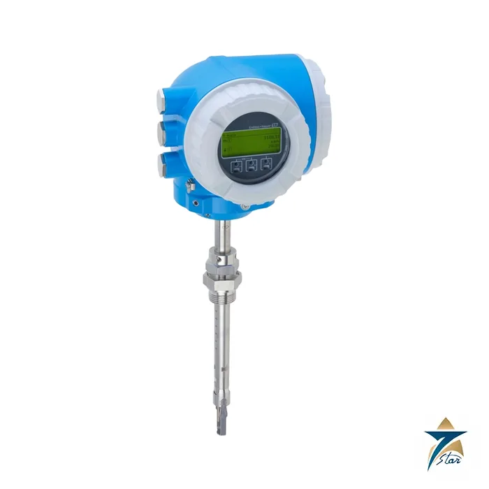
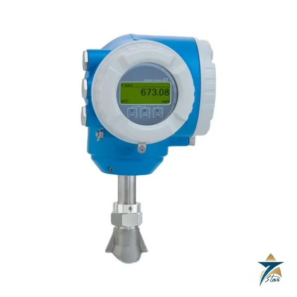
The Endress+Hauser t-mass I 300 (product root 6I3B) is an insertion thermal mass flowmeter for gas in circular pipes from DN 80 to 1500 (3 to 60″) and in rectangular ducts. A probe carrying the sensing element is pushed into the pipe through a single tapping, so a large line can be measured without cutting out a spool or buying a full-bore meter. The Proline 300 transmitter sits on the probe as a compact unit with a backlit touch display, WLAN access and up to three I/Os. Seven Star LLC supplies Endress+Hauser instruments in Oman and the GCC as an independent supplier in Muscat, and this page covers the points that matter when specifying the t-mass I 300.
Understanding the t-mass I 300 type
The letter I stands for insertion, 3 for the compact Proline 300 transmitter, and the sensor is available in several lengths and tapping styles. The sensor lengths listed in the datasheet are 235 mm (9″), 335 mm (13″), 435 mm (17″) and 608 mm (24″), and the minimum insertion depth is 100 mm in each case. The sensing element is stainless steel 1.4404 (316/316L), with an Alloy C22 (2.4602) version for corrosive gases. The probe itself is 1.4404; the connecting part to the transmitter, which does not touch the medium, is 1.4301 (304). The remote-transmitter sibling is the t-mass I 500.
t-mass I 300 technical specifications
| Parameter |
Specification |
| Manufacturer / part number |
Endress+Hauser / t-mass I 300 (6I3B) |
| Measuring principle |
Thermal mass flow, insertion probe, Gas Engine for 21 gases and mixtures |
| Nominal diameter |
DN 80 to 1500 (3 to 60″), circular pipes and rectangular ducts |
| Measuring range |
20 to 733501 kg/h (44 to 1669340 lb/h), depending on gas and pipe size |
| Operable flow range |
200:1 with factory calibration |
| Max. measurement error (gas) |
1.0 % of reading from 10 to 100 % of full scale; 0.1 % of full scale from 1 to 10 % |
| Repeatability / response |
±0.25 % of reading above 1.0 m/s; typically below 3 s for 63 % of a step change |
| Medium temperature |
–40 to +180 °C (–40 to +356 °F), seals and ferrules limit this (see below) |
| Medium pressure |
–0.5 to 20 bar gauge (–7.25 to 290 psig) |
| Sensor lengths |
235 / 335 / 435 / 608 mm; insertion depth from 100 mm up to full length |
| Wetted materials |
Insertion tube and sensing element 1.4404 (316/316L); Alloy C22 option; process coupling 1.4404 |
| Ambient temperature |
–40 to +60 °C (–50 °C with option JP) |
| Power supply |
DC 24 V ±20 % or AC 100 to 240 V; max. 10 W |
| Outputs |
HART 4–20 mA, Modbus RS485, pulse/frequency/switch, relay, current input, status input |
| Functional safety |
Patented drift-free sensor with SIL 2 (application package) |
How insertion measurement works
The probe holds a heated resistance thermometer and a temperature reference. As gas passes the heated element it removes heat, and the electronics adjust the power to keep a constant temperature difference. That power maps to local mass velocity at the sensor position. Because an insertion sensor reads at one point, the instrument converts it to total flow using the pipe cross-section and the velocity profile, which is why the correct inner diameter and a well-developed profile are essential. The Gas Engine handles gas properties, and the meter is calibrated on air.
Insertion depth, seals and hot tap options
The insertion depth follows the datasheet formula: depth = (0.3 × A) + B + (C1 + C2), where A is the pipe inner diameter (or duct inner dimension), B is the wall thickness, and C1 + C2 is the mounting kit plus the sensor compression fitting. With Endress+Hauser mounting bosses C1 + C2 is 112 mm (1″ NPT), 106 mm (G1″), 108 mm (¾” NPT) or 105 mm (G¾”). The depth must lie within the adjustment range of the chosen tube length, for example 100 to 335 mm for the 335 mm sensor. The metal ferrules deform on first installation, so the depth is fixed afterwards and the ferrule cannot be reused.
| Component |
Material |
Temperature limit |
| Sealing ring |
EPDM |
–40 to +140 °C |
| Sealing ring |
FKM |
–40 to +180 °C |
| Ferrule |
PEEK |
–40 to +140 °C |
| Ferrule |
PVDF |
–20 to +110 °C |
| Ferrule |
1.4404 |
–40 to +180 °C |
Cold and hot tap assemblies allow the probe to be inserted or withdrawn under pressure. The medium-pressure version is rated for 20 bar process pressure and 16 bar extraction pressure with a maximum extraction temperature of +50 °C and a minimum sensor length of 435 mm. A low-pressure version is rated for 4.5 bar extraction. The datasheet restricts hot-tap use at process pressure to non-toxic, innocuous gases.
Where the t-mass I 300 fits and related models
Use the t-mass I 300 for large pipes and ducts where an inline flanged meter would be too expensive or heavy: combustion air ducts, flue gas side-streams after clean-up, aeration air headers, compressed air mains and fuel gas headers. Smaller lines belong to the inline t-mass F 300 or F 500, which cover DN 15 to 100, and the basic compressed-air meter is the t-mass A 150. If the transmitter should be away from the pipe, take the t-mass I 500 with the same probe.
Selection checklist for t-mass I 300
- Gas, composition, pressure and temperature; make sure the pressure stays within –0.5 to 20 bar gauge.
- Pipe inner diameter, wall thickness and shape (circular or rectangular duct), so that the insertion depth and sensor length can be calculated.
- Sensor length 235, 335, 435 or 608 mm and the tapping size (1″ or ¾, NPT or G).
- Fixed compression fitting, or cold/hot tap for removal under pressure.
- Sensing element material, standard 316L or Alloy C22 for corrosive gas.
- Seal and ferrule material that matches the gas temperature.
- Bidirectional or reverse flow detection, I/O, power supply and approvals.
Installation, commissioning and maintenance
Weld the nipple or boss in a position that allows a straight inlet before the probe. Control valves require a long inlet of about 50 × DN, and flow conditioners are recommended where this is not possible. The sensor arrow must point in the flow direction, and on a bidirectional sensor the element must be aligned within 3 degrees. For very wet gas, an inclined orientation of about 135 degrees helps prevent condensate sitting on the sensor. Support heavy hot-tap assemblies to protect the pipe, and clean the pipe after welding to keep particles away from the sensing element. Remove the protective cap from the sensing element before insertion.
Commissioning is carried out through the touch display wizards or WLAN. Because the single measuring point is critical, record the pipe diameter, insertion depth and sensor orientation on the commissioning sheet. Heartbeat Technology supports verification without pulling the probe in many cases.
Typical applications in Oman and the GCC
Large utility headers in refineries, gas processing plants, power stations and desalination complexes are typical targets, along with combustion-air and fuel-gas measurement for boilers and heaters, aeration air in wastewater plants and compressed-air mains in industrial zones. Large-diameter pipes are often laid outdoors, so the transmitter on the probe is exposed to sun, so consider a sunshield, and keep the ambient limit of +60 °C in mind. Sand-laden wind makes regular checking of the sensing element worthwhile after plant shutdowns.
Information to send with an RFQ for t-mass I 300
Provide the gas and composition, pipe outside diameter and wall thickness (or duct dimensions), flow range, pressure and temperature, available tapping, whether hot-tap withdrawal is required, I/O and power supply, and any approval or documentation requirement.
Documents and quotation
The Endress+Hauser technical information for the t-mass I 300 is attached on this page as a datasheet, including the insertion depth tables, cold and hot tap options and ordering features.
Send the order code or the pipe and gas data and Seven Star LLC will prepare a quotation for Oman and the GCC.
Other Models in the Eh Tmass Thermal Range
Seven Star LLC supplies models from the Eh Tmass Thermal range in Oman and the GCC. Compare the related models below and request a quote for the one that matches your application.



















Reviews
There are no reviews yet.