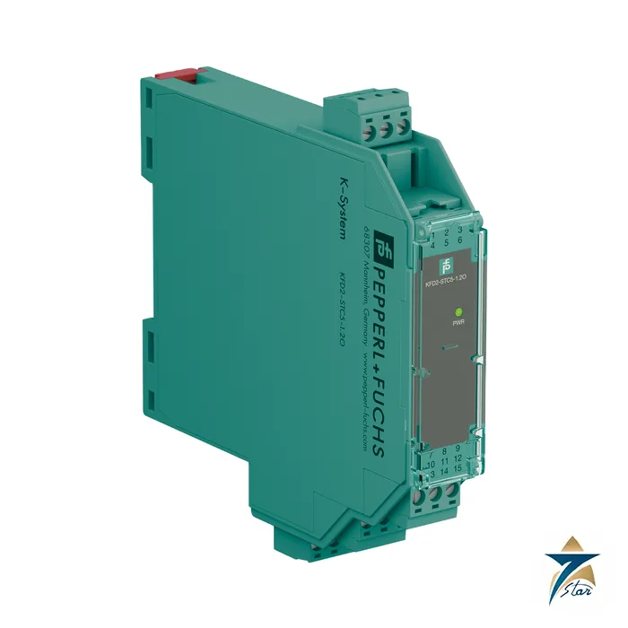
KFD2-STC5-1.2O SMART transmitter power supply with two outputs
The KFD2-STC5-1.2O takes one 4-20 mA signal from a 2-wire or 3-wire SMART transmitter and delivers it as two separate, isolated 4-20 mA outputs. That is the classic signal splitter requirement: a single field instrument has to report to a control system and, for example, to an emergency shutdown system or a recorder, without those receivers influencing each other.
Seven Star LLC supplies the KFD2-STC5-1.2O in Oman and the GCC as an independent supplier in Muscat. The module is only 12.5 mm wide, which also makes it attractive when cabinet space is tight.
How to read KFD2-STC5-1.2O
Within the STC5 family the datasheets distinguish the siblings by their channel and output arrangement. KFD2-STC5-1 has one input and one output, KFD2-STC5-2 has two complete channels, and KFD2-STC5-1.2O has one input channel and two outputs; this datasheet describes it as a signal splitter with one input and two outputs and dual output 4 to 20 mA current sink or source.
The datasheet header lists up to SIL 2 (SC 3) according to IEC/EN 61508, while the functional-safety parameter table of the same document shows SIL 3. Because the two statements do not match, confirm the intended safety integrity level and the associated safety manual with the manufacturer before using the module in a safety instrumented function.
Technical specifications of the KFD2-STC5-1.2O
| Parameter |
Specification |
| Manufacturer / part number |
Pepperl+Fuchs / KFD2-STC5-1.2O |
| Function |
SMART transmitter power supply and signal splitter, 1 input / 2 outputs |
| Supported SMART protocols |
HART, BRAIN, Foxboro |
| Input signal |
4 … 20 mA, terminals 1+, 2-, 3 |
| Available voltage to transmitter |
≥ 16 V at 20 mA; ≥ 20 V at 4 mA |
| Outputs |
Output 1: terminals 7 to 9; output 2: terminals 10 to 12; sink or source |
| Output load |
0 … 600 Ω per output; internal 250 Ω resistors at terminals 9 and 12 |
| External loop supply (sink mode) |
2 … 30 V DC |
| Supply |
18 … 30 V DC; power consumption ≤ 1.7 W at maximum load |
| Accuracy |
≤ 10 µA at 20 °C; drift ≤ 0.25 µA/K |
| Unused outputs |
Short-circuit unused output circuits; open outputs add up to 300 mW dissipation per channel |
| Ambient temperature |
-20 … 70 °C |
| Housing |
Type A2, 12.5 x 119 x 114 mm, approx. 100 g, 35 mm DIN rail, IP20 |
How the KFD2-STC5-1.2O splits the signal
The module powers the transmitter in the same way as the other STC5 devices and measures the loop current. The measured value is then reproduced on two output circuits that are isolated from the input. Each output can be wired as a current source or a current sink, so one output could drive an active analog input while the other works in a loop with an external supply of 2 to 30 V DC.
The datasheet gives a specific practical warning: unused output circuits should be short-circuited, because an open output raises the internal power dissipation by up to 300 mW per channel. In a densely packed cabinet this is a real heat consideration, and it is easy to overlook on a first installation. Each output also has its own 250 Ω resistor at terminals 9 and 12 for the HART resistance.
Digital HART signals are transferred between the field side and the control side, and the datasheet notes the bandwidth for 1 mA peak-to-peak and 1 V peak-to-peak signals in the two directions. Settling time is 500 µs and rise and fall time 100 µs.
Where the KFD2-STC5-1.2O is used
A splitter is the usual answer when a measurement must be shared between systems that must not interfere: a basic process control system and a safety system, a plant DCS and a local panel indicator, or a DCS and a remote monitoring package. Without isolation, a ground fault or an input fault in one receiver can corrupt the signal that the other receiver sees.
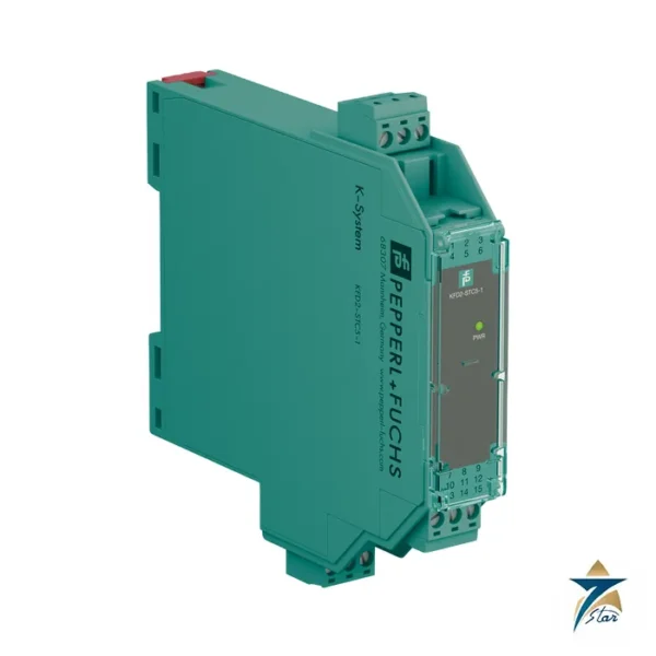
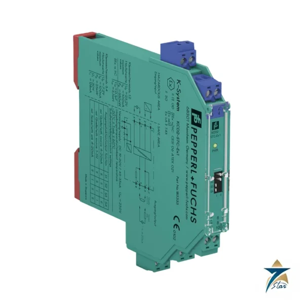
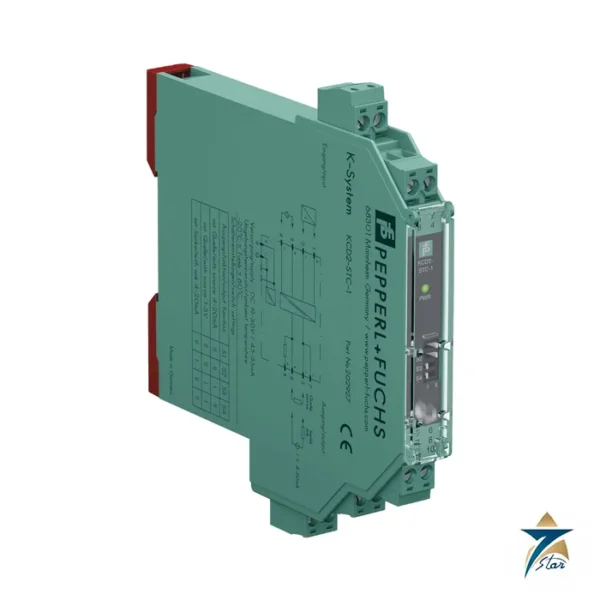
The KFD2-STC5-1 is the straightforward choice when only one receiver exists, and the KFD2-STC5-2 when two independent transmitters are connected. The KCD2-STC-1 is a narrow alternative with a voltage output option.
Selection and ordering checklist for the KFD2-STC5-1.2O
- Identify both receivers and their input impedance, and check the 0 to 600 Ω output load limit for each
- Decide sink or source mode per output
- Plan to short-circuit unused outputs
- Check HART communication requirements for each receiver
- Confirm the integrated safety level required and obtain the safety documentation
- Confirm Power Rail or terminal supply
Installation notes for the KFD2-STC5-1.2O
The module is only 12.5 mm wide, so a full row of them forms a very dense field. Leave air gaps if the cabinet runs warm, and keep the rail supply properly protected. Wire the transmitter to terminals 1+, 2- and 3 and the two receivers to the two output groups.
Commissioning is a loop check on each output: inject a known current at the transmitter side and verify both receivers. If either receiver is later removed for maintenance, short its output terminals so the dissipation figure in the datasheet is not exceeded.
Typical applications in Oman and the GCC
Splitter duty arises in oil and gas facilities where a pressure or level transmitter feeds both the process control system and the emergency shutdown system, and in power and desalination plants where the same measurement goes to a DCS and a separate protection or monitoring system. The 70 °C ambient rating supports installation in substation rooms and control containers typical of Gulf sites.
Signal splitter and standard transmitter supplies compared
From the manufacturer datasheets.
| Part number |
Inputs |
Outputs |
Housing width |
| KFD2-STC5-1 |
1 |
1 |
20 mm |
| KFD2-STC5-1.2O |
1 |
2 (isolated) |
12.5 mm |
| KFD2-STC5-2 |
2 |
2 (one per channel) |
20 mm |
Information to send with an RFQ for the KFD2-STC5-1.2O
Provide the following with your RFQ.
- Which two receivers the signal is split to
- Receiver input impedance and wiring mode
- HART requirement and safety integrity level needed
- Quantity and delivery date
Documents and quotation
The manufacturer datasheet for the KFD2-STC5-1.2O is attached on this page, so the electrical data, terminal assignment and ambient limits quoted above can be checked against the original document before an order is placed.
Seven Star LLC supplies Pepperl+Fuchs products in Oman and the GCC as an independent supplier in Muscat. Send the quantity, the signal types and the project delivery date, and we will confirm availability and lead time in a written quotation.
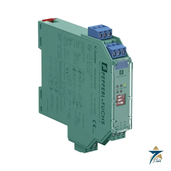
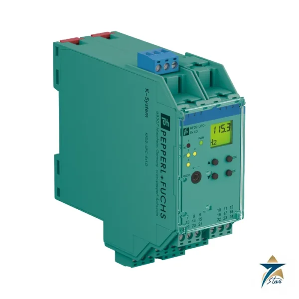
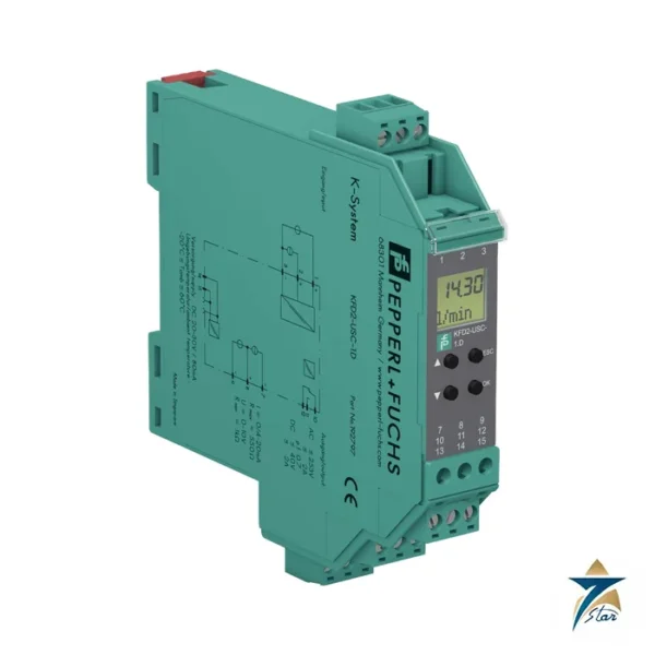
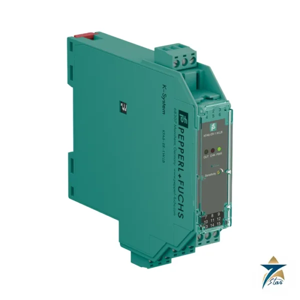
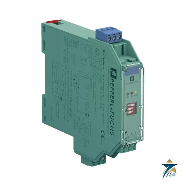
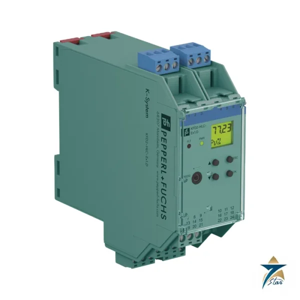
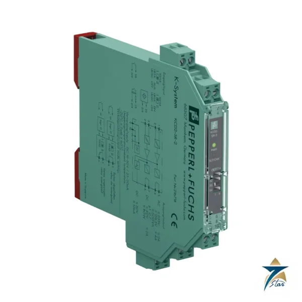
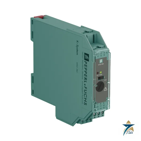
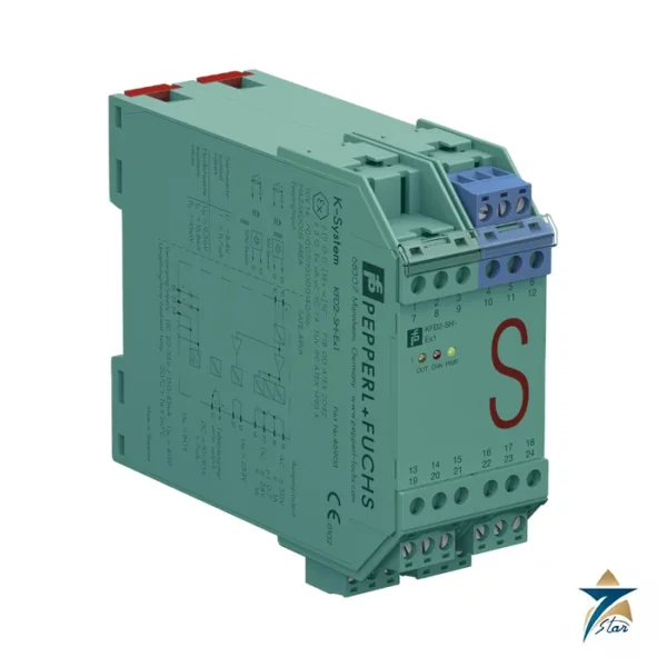
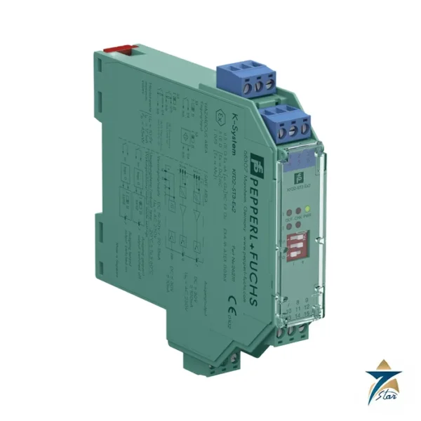
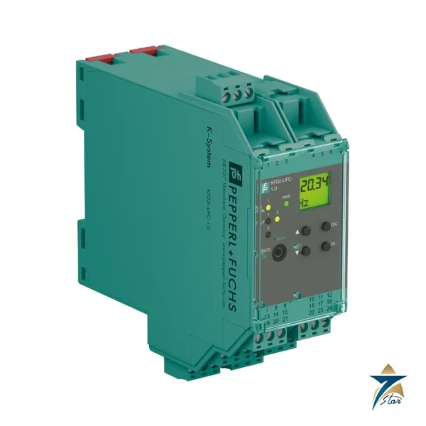
Other Models in the Pf Kfd2 Stc5 Range
Seven Star LLC supplies models from the Pf Kfd2 Stc5 range in Oman and the GCC. Compare the related models below and request a quote for the one that matches your application.



















Reviews
There are no reviews yet.