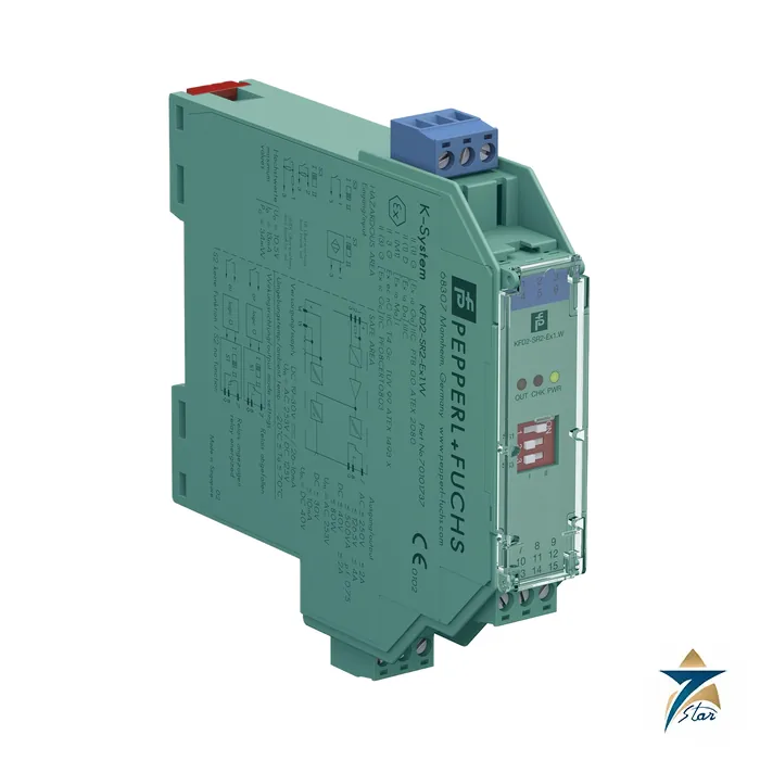
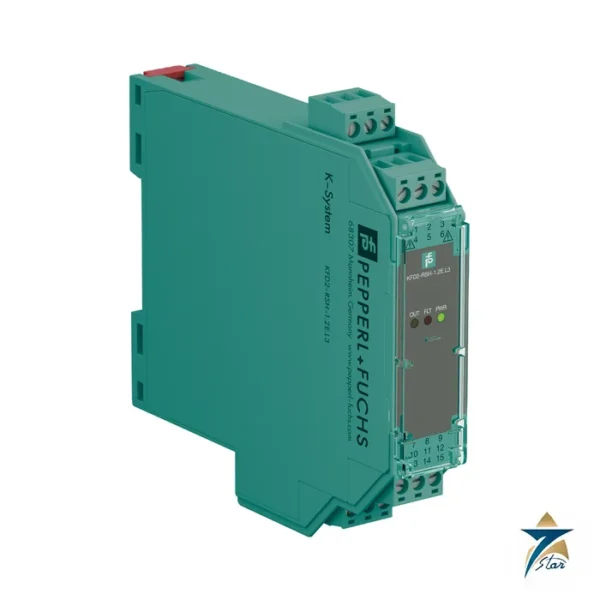
KFD2-SR2-Ex1.W single-channel relay switch amplifier
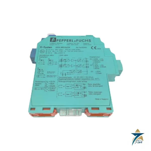
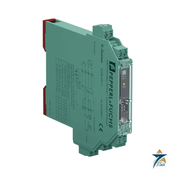
The KFD2-SR2-Ex1.W is the classic one-channel relay barrier of the Pepperl+Fuchs K-System. It takes a NAMUR proximity sensor or a mechanical contact from a hazardous area, isolates it, and switches a changeover relay in the safe area. It is one of the most widely used building blocks for position and status signals in process plants.
Decoding the part number: KFD2 for the 24 V DC isolated barrier, SR2 the relay switch amplifier generation 2, Ex1 one channel and .W the suffix used in the datasheet title for this relay version, which is rated down to -40 °C. The two-channel version is the KFD2-SR2-Ex2.W.
Seven Star LLC supplies this module in Oman and the GCC as an independent supplier in Muscat.
Technical specifications of the KFD2-SR2-Ex1.W
| Parameter |
Specification |
| Manufacturer / part number |
Pepperl+Fuchs KFD2-SR2-Ex1.W |
| Input |
NAMUR sensor or dry contact, EN 60947-5-6; terminals 1+, 2+, 3- |
| Open circuit voltage / short-circuit current |
approx. 8 V DC / approx. 8 mA |
| Switching point / hysteresis |
1.2 to 2.1 mA / approx. 0.2 mA |
| Line fault detection |
Breakage I ≤ 0.1 mA, short-circuit I > 6 mA |
| Output |
1 relay changeover, terminals 7, 8, 9; 250 V AC / 2 A, 126.5 V AC / 4 A, 40 V DC / 2 A resistive; min. 2 mA at 24 V DC |
| Delay / life |
approx. 20 ms energize and de-energize; 107 cycles; frequency < 10 Hz |
| Supply |
19 to 30 V DC, Power Rail or terminals 14+/15-; ≤ 35 mA, ≤ 0.7 W |
| Functional safety |
SIL 2, SC 3 acc. to IEC/EN 61508 |
| Hazardous area data |
PTB 00 ATEX 2080, [Ex ia Ga] IIC; Uo 10.5 V, Io 13 mA, Po 34 mW; TUV 99 ATEX 1493 X, II 3G Ex ec nC IIC T4 Gc |
| Isolation |
Reinforced, 300 Veff input/output, input/supply, output/supply |
| Ambient temperature |
-40 to 70 °C |
| Housing |
Type B2, 20 x 119 x 115 mm, IP20, approx. 150 g |
How the KFD2-SR2-Ex1.W behaves in normal and fault conditions
A NAMUR sensor changes its loop current across the 1.2 to 2.1 mA window; the KFD2-SR2-Ex1.W follows with a relay change after about 20 ms. DIP switches reverse the relay logic and can disable line fault detection for plain contacts. In a fault condition (cut cable below 0.1 mA, short above 6 mA) the relay drops to its de-energized state and an LED indicates the condition per NAMUR NE 44.
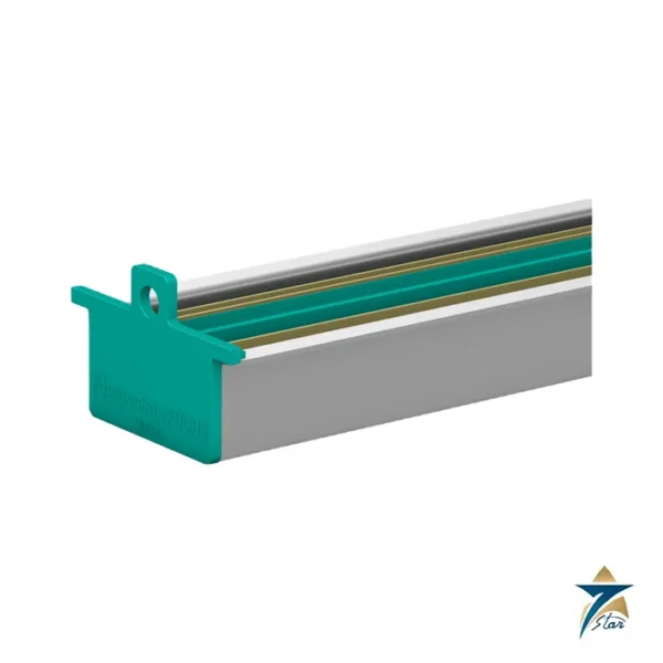
When mounted on a Power Rail, a collective error message is fed to the rail so a single alarm summarizes all modules. The relay output is potential-free, so it can switch mains-voltage coils or 24 V DC lamps within the contact ratings.
System fit and related parts
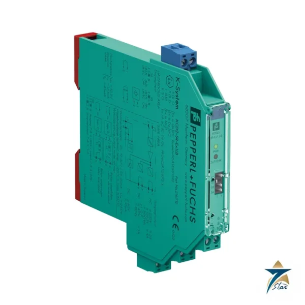
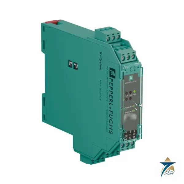
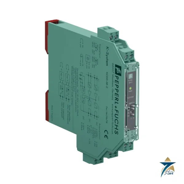
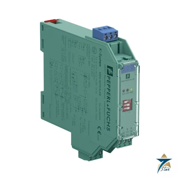
The relay of the KFD2-SR2-Ex1.W suits legacy or hard-wired panels, solenoid circuits and interposing relays. Where the PLC card is electronic and a 200 µs response is needed, the KFD2-SOT3-Ex1.LB is faster. In tight racks, the KCD2-SR-Ex1.LB gives two relays in 12.5 mm. The related KFD2-SR2-Ex2.W provides two channels in the same housing width.
Selection and ordering checklist
- Sensor is NAMUR or a contact with the resistor network.
- Check relay load, including inductive loads (cos phi above 0.75).
- Check -40 to 70 °C against the cabinet.
- Normal or reversed relay action.
- Ex ia data of the sensor against the module output values.
- Supply or Power Rail.
Installation, commissioning and maintenance of the KFD2-SR2-Ex1.W
Mount on DIN rail, wire the sensor to terminals 1+, 2+ and 3-, set the DIP switches and check each state of the sensor and the cable. For high-cycle signals consider the 10 million operation relay life and plan replacement; for inductive loads use suppression across the coil.
Keep a spare module available for critical loops and document switch positions to make like-for-like replacement quick.
Common wiring and troubleshooting points
Most field complaints on a KFD2-SR2-Ex1.W loop come from the sensor wiring rather than the module. A relay that never switches usually means the loop current stays outside the 1.2 to 2.1 mA window, for example because a 3-wire sensor was connected instead of a NAMUR type or the resistor pair on a contact is missing. A relay that chatters points to water in a junction box or a marginal contact.
Check the LED against the cable: with line fault detection on, a lit fault LED and a de-energized relay mean breakage or short. Measure the loop current with the cable disconnected from terminals 1+ and 3- while respecting the hazardous-area rules for live work, and compare with the 8 mA short-circuit figure from the datasheet. Always replace a failed module with the same part number, because DIP defaults and relay wiring differ between versions.
Typical applications in Oman and the GCC
The KFD2-SR2-Ex1.W is applied to valve limit switches, tank level switches and motor status contacts across upstream oil and gas, refineries, power plants and desalination sites in the GCC, often in hot cabinets where the -40 to 70 °C rating gives headroom.
Family comparison
| Part |
Key difference |
| KFD2-SR2-Ex1.W (this part) |
1 channel, 1 relay, 20 mm, -40 to 70 °C |
| KFD2-SR2-Ex2.W |
2 channels, 1 relay each |
| KCD2-SR-Ex1.LB |
1 channel, 2 relays, 12.5 mm |
| KFD2-SH-Ex1 |
Safety version, SIL 3 |
Information to send with an RFQ
- Part number KFD2-SR2-Ex1.W and quantity
- Sensor type and Ex data
- Relay load type and voltage
- Supply method
- Delivery location
Documents and quotation
The manufacturer datasheet for KFD2-SR2-Ex1.W is attached on this page, so you can check wiring, approvals and dimensions before ordering. Send the exact part number, quantity and delivery location in Oman or the GCC and Seven Star LLC will reply with a quotation.
Seven Star LLC is an independent supplier in Muscat and is not the manufacturer; confirm availability, lead time and any project approval requirements in your RFQ.



















Reviews
There are no reviews yet.