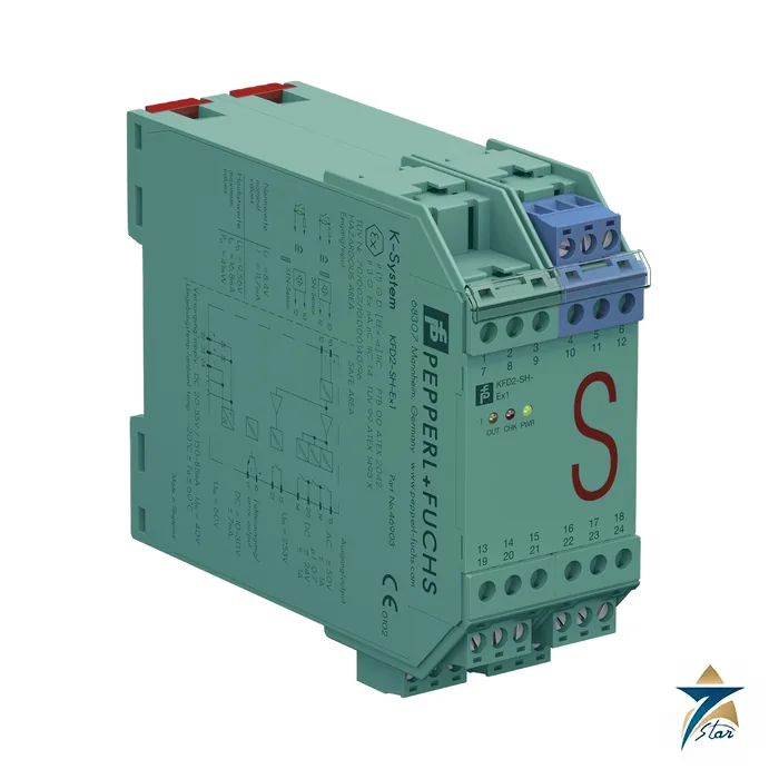
KFD2-SH-Ex1 safety switch amplifier for SIL 3 applications
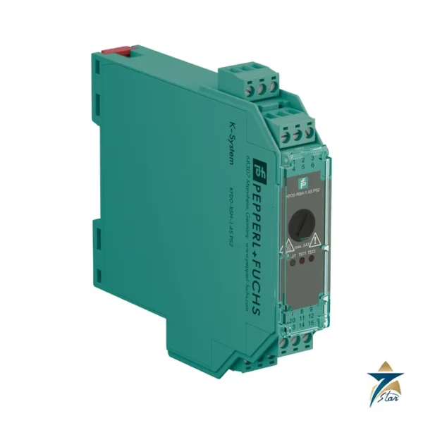
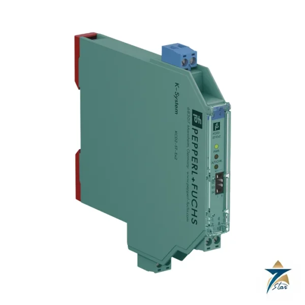
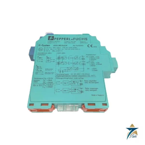
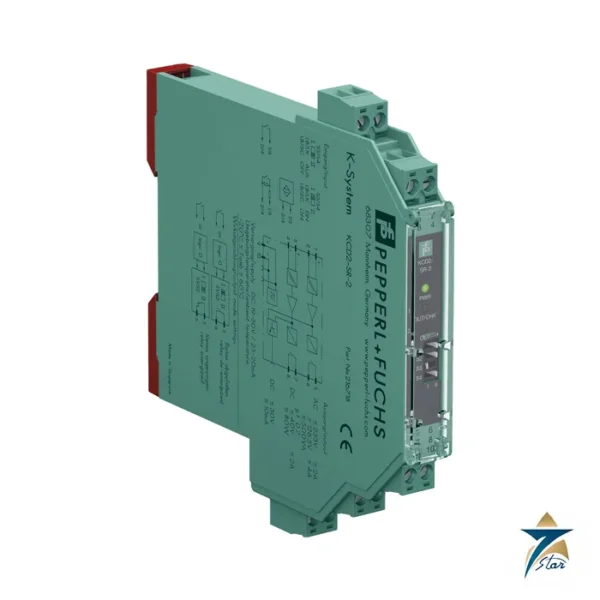
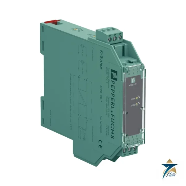
The KFD2-SH-Ex1 is a one-channel isolated barrier from Pepperl+Fuchs designed for safety-related shutdown circuits. It reads an SN or S1N proximity sensor, or an approved dry contact, from a hazardous area and drives three outputs: a relay with three normally-open contacts (two in series for the safety function), a relay with one normally-open contact, and a passive transistor output that reports lead breakage or short-circuit.
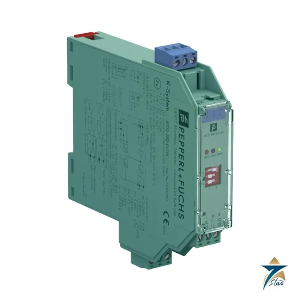
In the name, KFD2 is the 24 V DC barrier range, SH the safety (Sicherheits) switch amplifier and Ex1 one channel. Standard NAMUR repeaters like the KFD2-SR2-Ex1.W are rated SIL 2; the KFD2-SH-Ex1 is the one with SIL 3 and PL d on its datasheet.
Seven Star LLC supplies the module in Oman and the GCC as an independent supplier in Muscat.
Technical specifications of the KFD2-SH-Ex1
| Parameter |
Specification |
| Manufacturer / part number |
Pepperl+Fuchs KFD2-SH-Ex1 |
| Input |
SN/S1N sensors or approved passive dry contacts; terminals 10+, 12-; open circuit about 8.4 V DC, short-circuit about 11.7 mA |
| Switching points |
Relay energized for 2.8 to 5.3 mA; de-energized below 2.1 mA and above 5.9 mA |
| Lead resistance / response delay |
≤ 50 Ω / ≤ 1 ms |
| Output I |
Relay, terminals 13/14, 50 V AC / 1 A, 24 V DC / 1 A resistive; mechanical life 50 million cycles |
| Output II |
Relay, terminals 15/21, same ratings |
| Output III |
Passive transistor fault output, 10 to 30 V DC, 7 mA, short-circuit proof |
| Switching frequency |
5 Hz |
| Supply |
20 to 35 V DC, Power Rail or terminals 22+, 23+, 24-; ≤ 130 mA, 2.3 W max. |
| Functional safety |
SIL 3 / SC 3 acc. to IEC/EN 61508; PL d acc. to EN ISO 13849 |
| Hazardous area data |
PTB 00 ATEX 2042, [Ex ia Ga] IIC; Uo 9.56 V, Io 16.8 mA, Po 41 mW; TUV 99 ATEX 1493 X, II 3G Ex ec nC IIC T4 Gc |
| Ambient temperature |
-20 to 60 °C |
| Housing |
Type C1, 40 x 107 x 115 mm, IP20, approx. 280 g, removable terminals |
How the KFD2-SH-Ex1 supports the safety function
For single-channel operation up to SIL 3 the safety contacts on terminals 13 and 14 (output I) must be used; SIL 2 applications may also use output II. The center tap of the contacts (terminals 19 and 20) allows a redundant branch. The input is continuously monitored for lead breakage and short-circuit: on a fault the fault output energizes and outputs I and II de-energize, so the safe state is a dropped relay.
The datasheet points out that a mechanical contact needs a 10 kΩ resistor in parallel and a 1.5 kΩ resistor in series, unlike an SN/S1N sensor. The input may only be used with potential-free (passive) switches. Anyone using the module in a safety function should follow the test documents and safety manual, including proof test intervals.
System fit and related parts
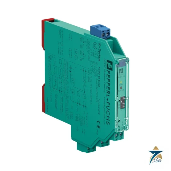
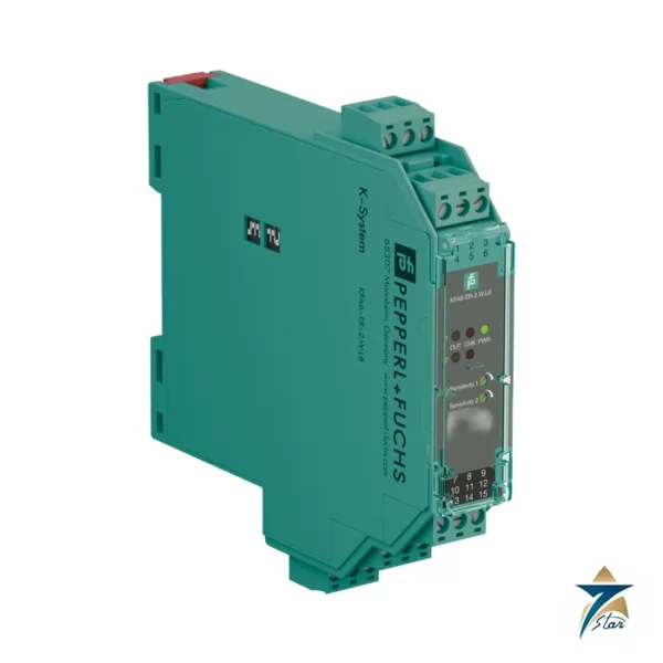
Common fields for the KFD2-SH-Ex1 are emergency shutdown limit switches, door or guard interlocks in hazardous areas, and valve position proofs feeding a safety PLC or hard-wired trip chain. For non-safety signals, the cheaper KFD2-SR2-Ex1.W or the 12.5 mm KCD2-SR-Ex1.LB avoid the extra width and the 2.3 W consumption.
Selection and ordering checklist
- Required SIL or PL and the architecture (single channel up to SIL 3 on output I).
- Sensor type: SN/S1N or passive contact with the resistor network.
- Relay load: 50 V AC or 24 V DC at 1 A.
- Use of the fault output (transistor, 10 to 30 V DC, 7 mA).
- Supply 20 to 35 V DC and heat load of 2.1 W dissipation.
- Ex ia data of the sensor against Uo 9.56 V, Io 16.8 mA, Po 41 mW.
Installation, commissioning and maintenance of the KFD2-SH-Ex1
Mount on DIN rail with the removable terminals fitted and observe separation of the intrinsically safe terminals. At commissioning, test every state: actuated, released, open loop and shorted loop, confirming each relay and the fault output. Record the results in the safety validation file.
Perform proof tests at the interval stated in the safety manual, replace relays at end of life, and keep a tested spare because a failed safety barrier will normally mean a plant shutdown.
Safety documentation and proof testing for the KFD2-SH-Ex1
A SIL 3 claim only counts when the whole loop is assessed: sensor, cable, barrier and logic solver. The datasheet of the KFD2-SH-Ex1 lists SIL 3 with SC 3 and PL d, and the failure rates, safe failure fraction and proof-test intervals are in the safety manual that the manufacturer publishes with the product. Ask for it in your RFQ if the project needs it.
Proof testing should operate the actual sensor, confirm the relay contacts open and close, and verify the fault output on a simulated cable break. Since output I must be used for SIL 3, make sure the wiring drawings label the correct terminals 13 and 14 so that maintenance staff do not move the safety signal to terminals 15 and 21.
Typical applications in Oman and the GCC
The KFD2-SH-Ex1 appears in emergency shutdown and burner management circuits at gas processing, refining and power plants in Oman, in desalination chemical stores and in loading terminals where classified-area sensors feed safety logic.
Family comparison
| Part |
Key difference |
| KFD2-SH-Ex1 (this part) |
SIL 3 / PL d, 2 relays + fault transistor output, 40 mm |
| KFD2-SR2-Ex1.W |
SIL 2, 1 relay, 20 mm |
| KCD2-SR-Ex1.LB |
SIL 2, 2 relays, 12.5 mm |
| KFD2-SOT3-Ex1.LB |
SIL 2, 2 transistor outputs |
Information to send with an RFQ
- Part number KFD2-SH-Ex1 and quantity
- Required SIL or PL
- Sensor type and Ex data
- Relay load
- Supply method
- Delivery location
Documents and quotation
The manufacturer datasheet for KFD2-SH-Ex1 is attached on this page, so you can check wiring, approvals and dimensions before ordering. Send the exact part number, quantity and delivery location in Oman or the GCC and Seven Star LLC will reply with a quotation.
Seven Star LLC is an independent supplier in Muscat and is not the manufacturer; confirm availability, lead time and any project approval requirements in your RFQ.



















Reviews
There are no reviews yet.