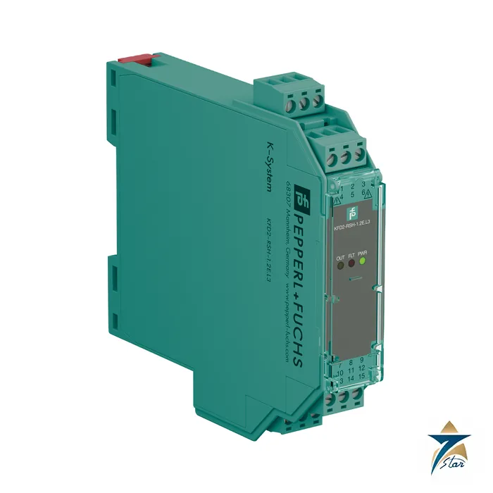
KFD2-RSH-1.2E.L3 relay module for safe switching of load circuits
The KFD2-RSH-1.2E.L3 is a relay module that switches a load circuit of up to 230 V AC from a 24 V DC control output while keeping the two circuits galvanically isolated. It is designed for safety applications: the energized to safe (ETS) function is permitted for SIL 3, and the module reports a wiring fault in the load circuit back to the controller through a change of the input impedance, a function called line fault transparency.
Seven Star LLC supplies the KFD2-RSH-1.2E.L3 in Oman and the GCC as an independent supplier in Muscat. The sections below explain the function and what to check before ordering.
KFD2-RSH-1.2E.L3 designation
The KFD2-RSH-1.2E.L3 is a type designation of the Pepperl+Fuchs K-System, named in the datasheet as a relay module, a 1-channel signal conditioner with 24 V DC supply. The datasheet states up to SIL 3 according to IEC/EN 61508 and systematic capability SC 3. The validity of safety figures depends on following the safety manual for the exact device, so treat the type string including the suffixes as the unit of ordering.
Technical specifications of the KFD2-RSH-1.2E.L3
| Parameter |
Specification |
| Manufacturer / part number |
Pepperl+Fuchs / KFD2-RSH-1.2E.L3 |
| Function |
Relay module, digital output, energized to safe, line fault transparency |
| Control input |
19 … 26.4 V DC (1-signal), -5 … 5 V DC (0-signal); terminals 7+, 8- |
| Input current |
max. 35 mA at 24 V DC; max. 44 mA at 19 V DC with internal fault detection enabled |
| Test pulse |
max. 2 ms from the DO card |
| Switched voltage |
50 … 230 V AC; 60 … 110 V DC |
| Contact rating |
253 V AC / 5 A / cos φ 0.7; 30 V DC / 5 A resistive; min. 10 mA |
| Mechanical life |
5 x 10⁶ cycles |
| Line fault detection |
Undercurrent 10 mA AC; overcurrent 5.5 A AC; breakage 48 kΩ; short-circuit 29 Ω |
| Fault indication output |
Terminals 10, 11; 30 V DC / 0.5 A; reaction time < 2 s |
| Switching frequency |
< 3 Hz (fault detection disabled); < 0.5 Hz (enabled) |
| Power consumption |
< 1.7 W; dissipation < 3.3 W at 5 A |
| Functional safety |
SIL 3, SC 3 (IEC/EN 61508) |
| Ambient temperature |
-20 … 60 °C |
| Housing |
Type B2, 20 x 119 x 115 mm, approx. 134 g, 35 mm DIN rail, IP20 |
How energized to safe and line fault transparency work
In an energized to safe (ETS) arrangement the safe state, such as a valve closed or a drive stopped, is reached when the output is energized, so that the module must actively drive the contact to reach the safe condition. This is the opposite of the usual de-energize-to-trip behaviour and is used in fire-and-gas and some shutdown systems.
Line fault transparency means that the controller can see wiring faults in the load circuit through the impedance of the digital output channel. The module monitors the load circuit for low voltage, undercurrent (10 mA AC), overcurrent (5.5 A AC) and for breakage (48 kΩ) or short circuit (29 Ω) of the load while the relay is de-energized. The fault shows up as a change of impedance at the DO card and as an additional relay contact output at terminals 10 and 11.
When internal fault detection is enabled, the minimum pulse and pause times lengthen to 1 s and the switching frequency drops below 0.5 Hz; this is acceptable for valve and shutdown duty but not for fast cycling.
Where the KFD2-RSH-1.2E.L3 belongs in a safety loop
It is used between a safety DO card and a solenoid, a contactor or a signal at 110 to 230 V, which a safety PLC output cannot drive directly. The datasheet explicitly names loads up to 230 V AC and the 24 V DC control circuit as isolated from each other.
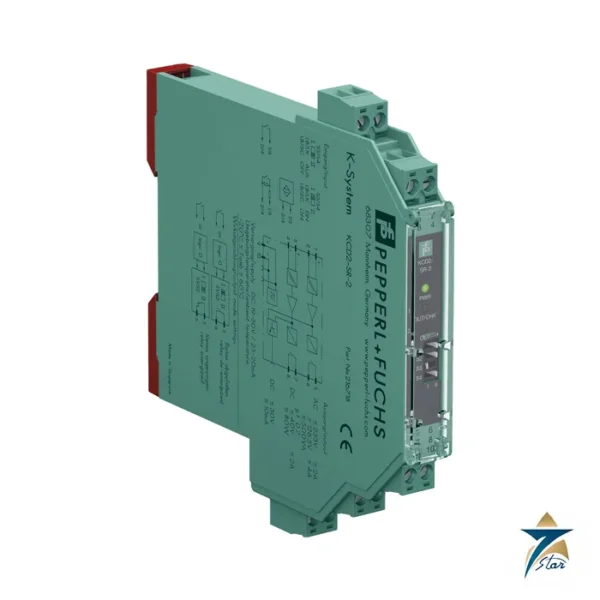
For NAMUR switching signals in the opposite direction, the KCD2-SR-2 is the corresponding input-side module.
Selection and ordering checklist for the KFD2-RSH-1.2E.L3
- Load voltage, current and type (AC or DC, inductive)
- Safety requirement: SIL 3 ETS function
- Whether internal fault detection is enabled and the resulting switching frequency
- Compatibility with the DO card test pulse and leakage current
- Heat dissipation at 5 A
- Supply through Power Rail or terminals
Installing and proving the KFD2-RSH-1.2E.L3
Wire the control signal to terminals 7+ and 8-, the load to terminals 5+/L, 2-/N, 6 and 3, and the fault contact to 10 and 11. Check the derating curves of the datasheet for the planned load current and ambient temperature, since dissipation reaches 3.3 W at 5 A.
Proof testing in safety loops should follow the manufacturer manual and the plant safety procedure. Test the line fault detection by simulating a broken and a shorted load wire.
Typical applications in Oman and the GCC
Relay modules of this type are used in emergency shutdown and fire-and-gas systems for solenoids, alarms and contactors in oil and gas facilities, and in boiler protection and burner management in power and desalination plants.
Relay and switch amplifier modules
From the datasheets.
| Part number |
Function |
Channels |
| KFD2-RSH-1.2E.L3 |
Load switching, SIL 3 ETS |
1 |
| KCD2-SR-2 |
NAMUR input, relay output |
2 |
| KCD2-SOT-2 |
NAMUR input, transistor output |
2 |
Information to send with an RFQ for the KFD2-RSH-1.2E.L3
Please include the following.
- Load type, voltage and current
- SIL requirement and the DO card model
- Supply arrangement
- Quantity and delivery date
Documents and quotation
The manufacturer datasheet for the KFD2-RSH-1.2E.L3 is attached on this page, so the electrical data, terminal assignment and ambient limits quoted above can be checked against the original document before an order is placed.
Seven Star LLC supplies Pepperl+Fuchs products in Oman and the GCC as an independent supplier in Muscat. Send the quantity, the signal types and the project delivery date, and we will confirm availability and lead time in a written quotation.
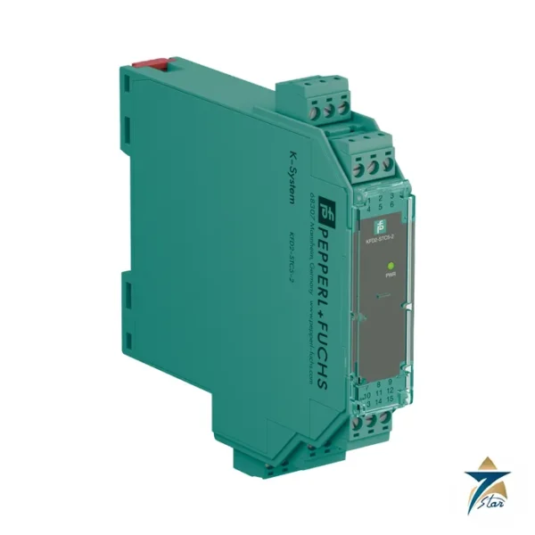
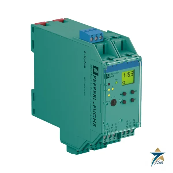
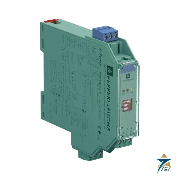
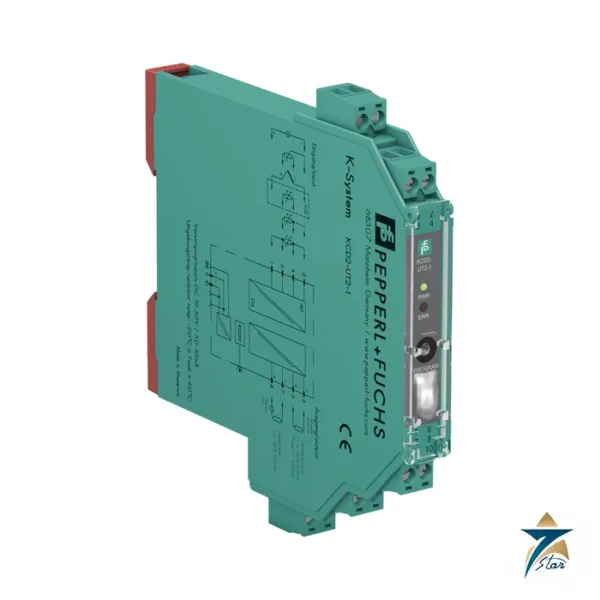
Other Models in the Pf Kfd2 Misc Range
Seven Star LLC supplies models from the Pf Kfd2 Misc range in Oman and the GCC. Compare the related models below and request a quote for the one that matches your application.



















Reviews
There are no reviews yet.