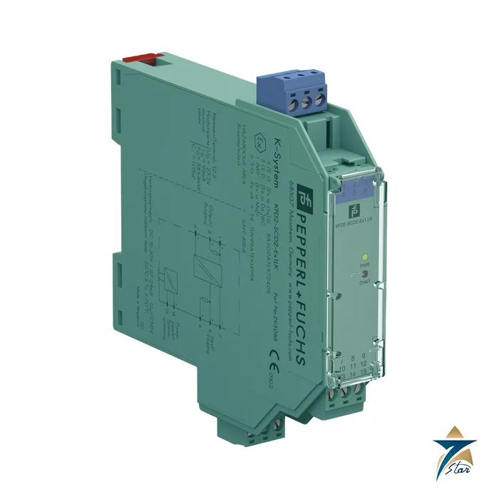
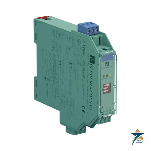
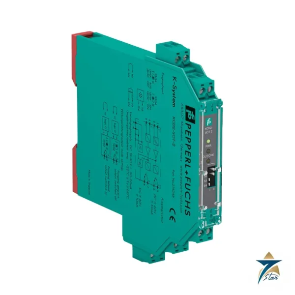
KFD2-SCD2-Ex1.LK SMART current driver for I/P converters and positioners
The KFD2-SCD2-Ex1.LK is a one-channel isolated barrier that works in the opposite direction to a transmitter power supply: it takes a 4 to 20 mA signal from the control system and delivers it to a device in the hazardous area, such as an I/P converter, an electric valve actuator or a smart valve positioner. HART signals ride on the loop in both directions, so a positioner can still be configured from the control room or a handheld.
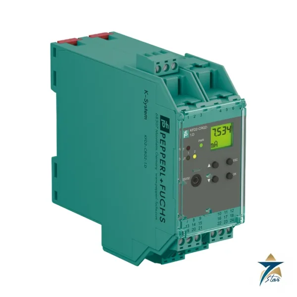
In the part number, KFD2 is the 24 V DC isolated barrier range, SCD2 the SMART current driver of the second generation, Ex1 a single channel, and the suffix .LK marks the version with line fault detection and an output that can handle up to 650 Ω loads. The KFD2-CD-Ex1.32 is a separate current driver type, so check its datasheet before treating the two as interchangeable.
Seven Star LLC supplies this module in Oman and the GCC as an independent supplier in Muscat.
Technical specifications of the KFD2-SCD2-Ex1.LK
| Parameter |
Specification |
| Manufacturer / part number |
Pepperl+Fuchs KFD2-SCD2-Ex1.LK |
| Input (control side) |
4 to 20 mA, limited to about 30 mA; terminals 7-, 8+, (9+); voltage drop about 6 V at 20 mA |
| Output (field side) |
4 to 20 mA; terminals 1+, 2- (with short-circuit detection) or 3+, 2- (without) |
| Load |
100 to 650 Ω on terminals 1/2; 0 to 550 Ω on terminals 2/3 |
| Available voltage |
≥ 13 V at 20 mA |
| Accuracy |
< 0.1 % of full scale incl. non-linearity and hysteresis |
| Temperature influence |
< 2 µA/K (-20 to 70 °C), < 4 µA/K (-40 to -20 °C) |
| Bandwidth / rise time |
0 to 3 kHz (-3 dB) / ≤ 10 ms |
| Line fault detection |
Breakage (load > 100 kΩ) and short-circuit (load < 50 Ω), fault bus output (open collector) |
| Supply |
19 to 30 V DC, Power Rail or terminals 14+/15-; ≤ 30 mA at 24 V, ≤ 600 mW at 20 mA and 500 Ω |
| Functional safety |
SIL 2, SC 3 acc. to IEC/EN 61508 |
| Hazardous area data |
BAS 00 ATEX 7240 X, [Ex ia Ga] IIC; Uo 25.2 V, Io 93 mA, Po 585.3 mW, Ci 1.05 nF |
| Ambient temperature |
-40 to 70 °C |
| Housing |
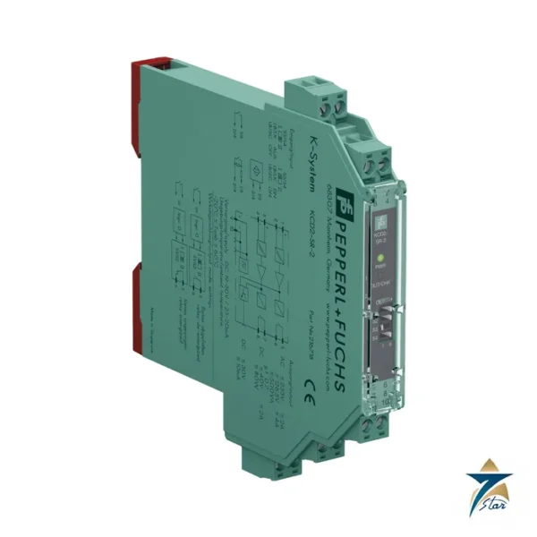
Type B2, 20 x 124 x 115 mm, IP20, approx. 115 g |
How the KFD2-SCD2-Ex1.LK drives the field loop
The 4 to 20 mA from the control card flows through a DC/DC converter stage and is repeated on terminals 1 and 2 of the KFD2-SCD2-Ex1.LK. If no short-circuit detection is wanted, terminals 3 and 2 are used instead, which also lowers the permitted load to 550 Ω. An open or shorted field circuit is presented to the control side as high impedance, so the control system sees the loop as failed and can raise an alarm.
HART communication passes through the barrier from either side. Where the HART communication resistance in the loop is too low, an internal 250 Ω can supply it, and test sockets for communicators are built into the terminals. Faults are shown on LEDs and put on a shared fault bus on the Power Rail.
System fit and related parts
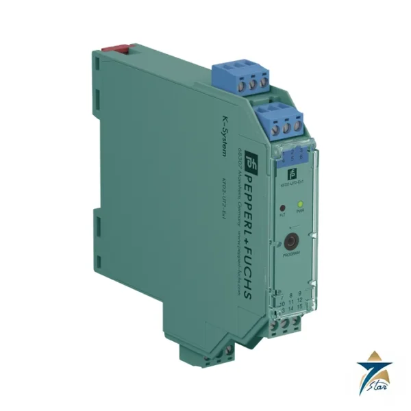
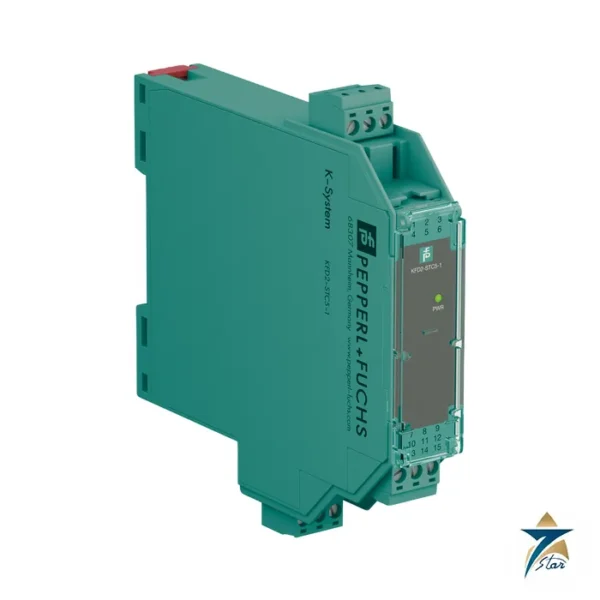
Typical loads for the KFD2-SCD2-Ex1.LK are smart positioners on control valves, I/P converters on pneumatic actuators and electrically driven valves, all located in Zone 0, 1 or 2. For a plain current driver, see KFD2-CD-Ex1.32; for the opposite signal direction (transmitters), use KFD2-STC5-1 or KCD2-STC-Ex1. A positioner with a high compliance voltage may demand the 650 Ω range, so check the loop budget against the 13 V available at 20 mA.
Selection and ordering checklist
- Confirm the load is a 4 to 20 mA device (I/P, positioner, valve actuator) and note its input resistance and minimum voltage.
- Check loop budget: load plus cable up to 650 Ω (or 550 Ω on terminals 3/2).
- Confirm Ex ia entity values against Uo 25.2 V, Io 93 mA, Po 585.3 mW and Ci 1.05 nF.
- Decide whether short-circuit detection is wanted (terminal choice).
- Check HART requirements and loop resistance.
- Verify supply and Power Rail availability.
Installation, commissioning and maintenance of the KFD2-SCD2-Ex1.LK
Mount on DIN rail, connect the control-side signal to terminals 7-, 8+ and the field to 1+, 2-, and keep intrinsically safe wiring separate. Drive the loop from 4 to 20 mA at the control system and verify the valve or I/P travels correctly; then simulate a cut and a short to confirm the control system detects the high-impedance condition.
For maintenance, track the valve positioner calibration separately from the barrier. If a loop shows low current or reads an alarm, check the LED first and the barrier supply, then test the field cable.
Typical applications in Oman and the GCC
The KFD2-SCD2-Ex1.LK is used for control valves on gas processing trains, wellhead choke and flow control, tank farm loading, and utilities in power plants and desalination plants across Oman. Valve positioners on hot sites benefit from the extended -40 to 70 °C range.
Family comparison
| Part |
Key difference |
| KFD2-SCD2-Ex1.LK (this part) |
SMART current driver, up to 650 Ω, HART, LFD |
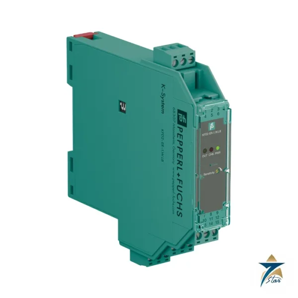
| KFD2-CD-Ex1.32 |
1-channel current driver for I/P converters and valve loops |
| KFD2-STC5-1 |
Transmitter power supply (input direction) |
| KCD2-STC-Ex1 |
12.5 mm transmitter power supply |
Information to send with an RFQ
- Part number KFD2-SCD2-Ex1.LK and quantity
- Valve positioner or I/P model with Ex data
- Loop resistance budget
- HART requirement
- Supply method
- Delivery location
Documents and quotation
The manufacturer datasheet for KFD2-SCD2-Ex1.LK is attached on this page, so you can check wiring, approvals and dimensions before ordering. Send the exact part number, quantity and delivery location in Oman or the GCC and Seven Star LLC will reply with a quotation.
Seven Star LLC is an independent supplier in Muscat and is not the manufacturer; confirm availability, lead time and any project approval requirements in your RFQ.



















Reviews
There are no reviews yet.