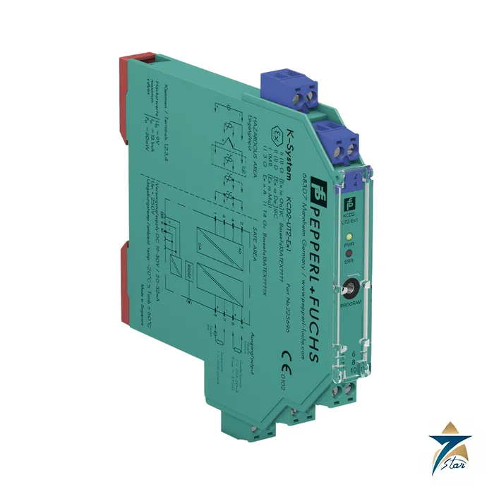
KCD2-UT2-Ex1 universal temperature converter in 12.5 mm
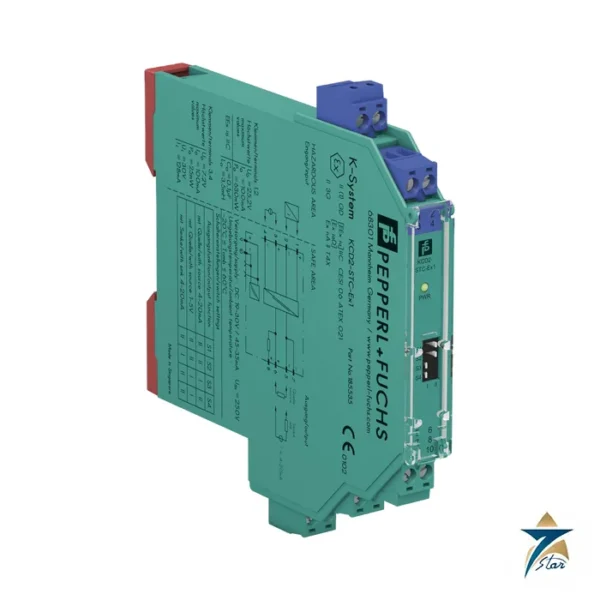
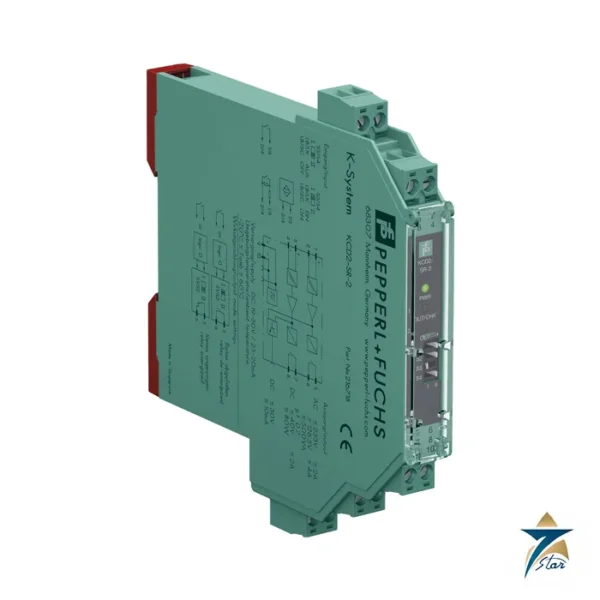
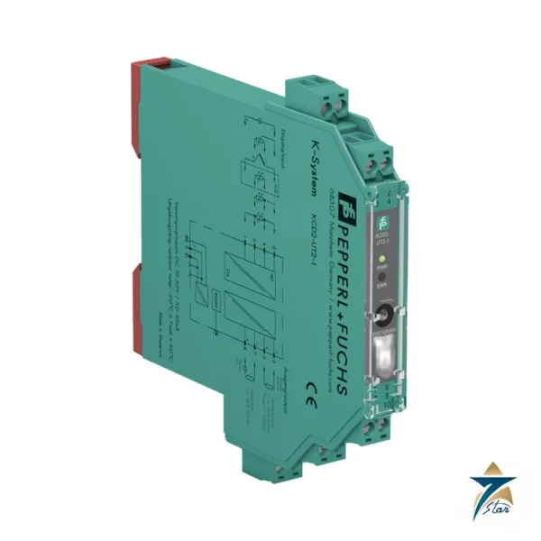
The KCD2-UT2-Ex1 is a one-channel PACTware-configured signal converter from the Pepperl+Fuchs KC-System. It reads resistance thermometers, thermocouples, potentiometers or low-level voltages from a hazardous area and converts them into a 0 or 4 to 20 mA signal in the safe area. The housing is only 12.5 mm wide, so many loops fit in one DIN rail row.
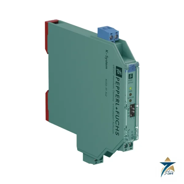
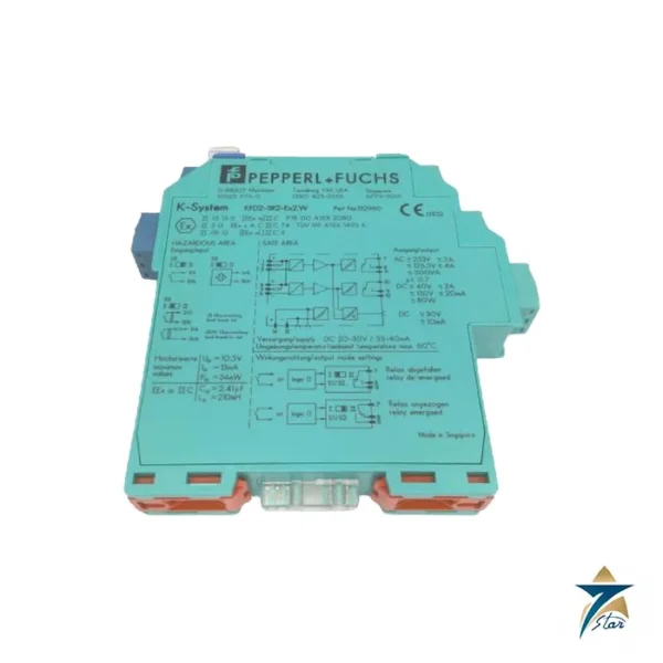
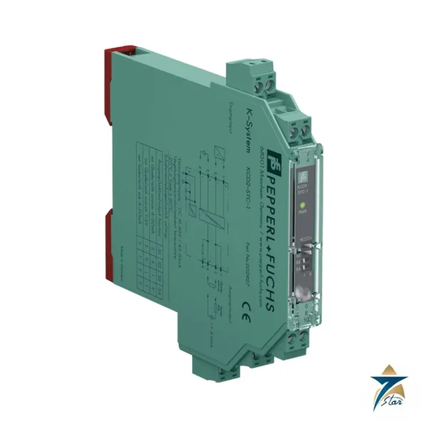
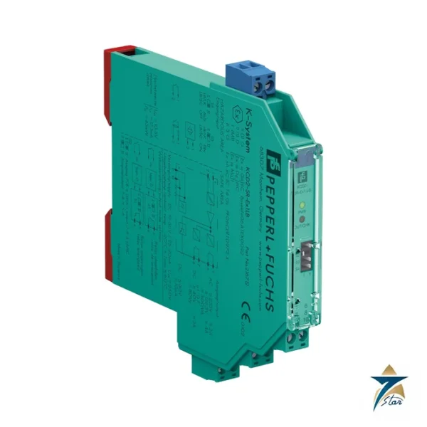
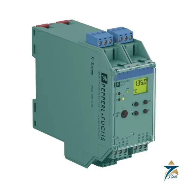
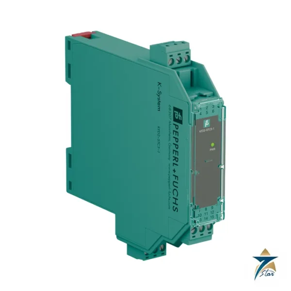
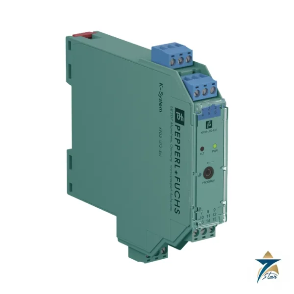
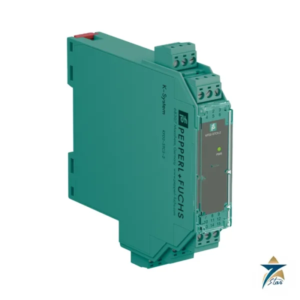
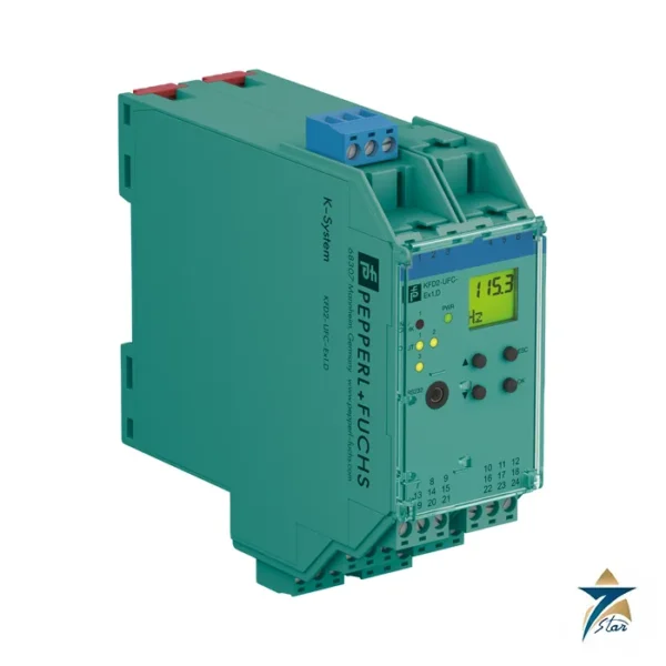
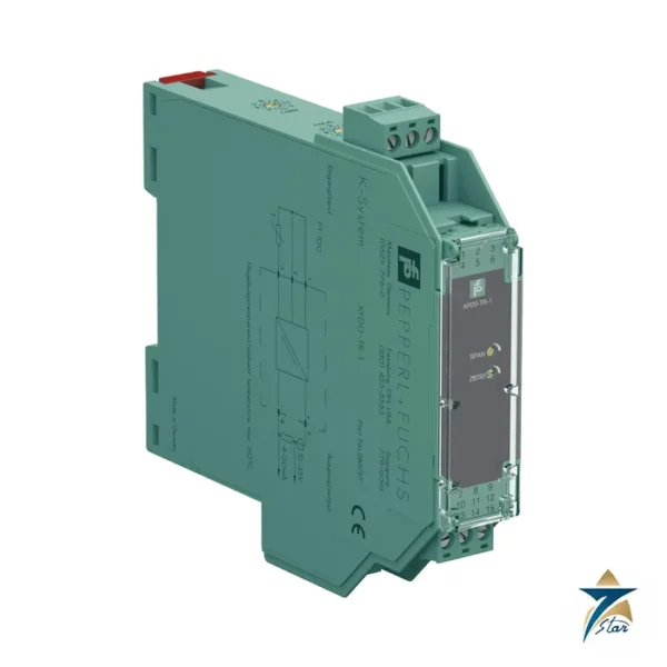
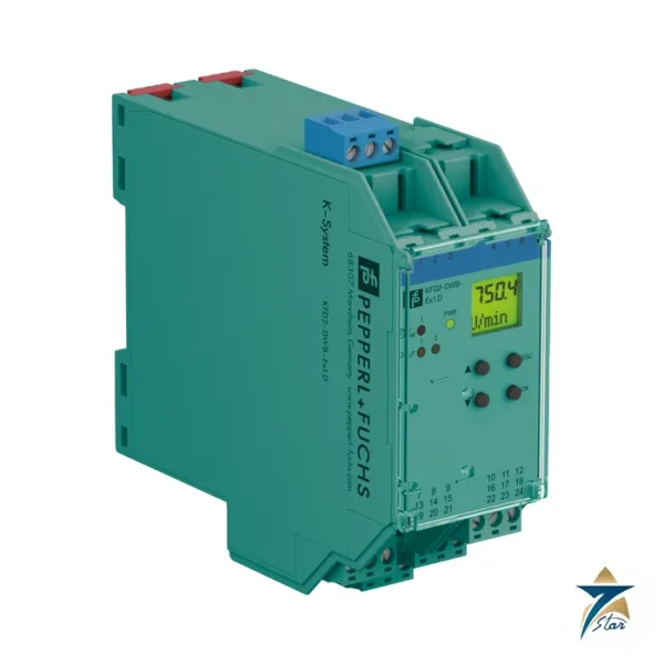
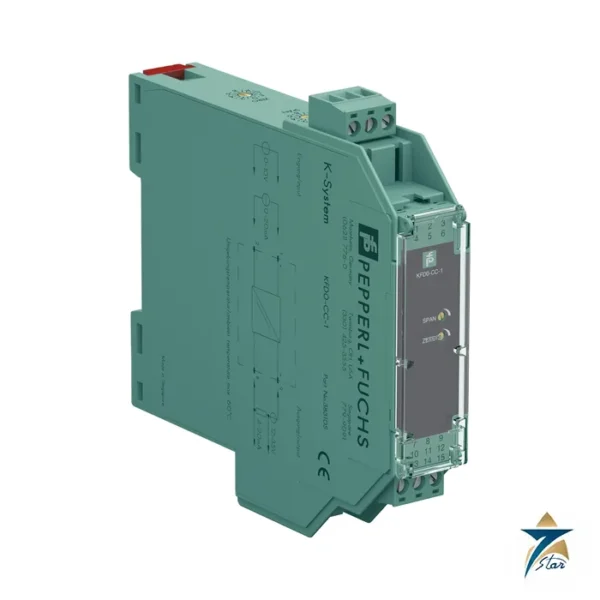
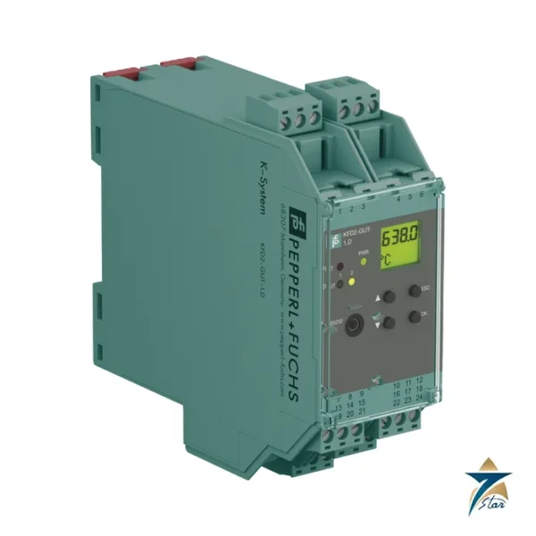
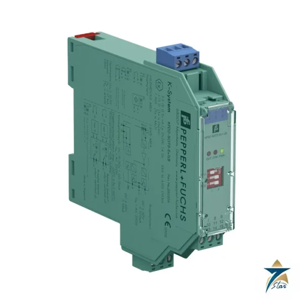
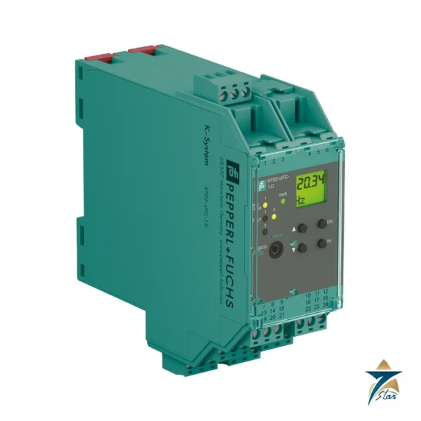
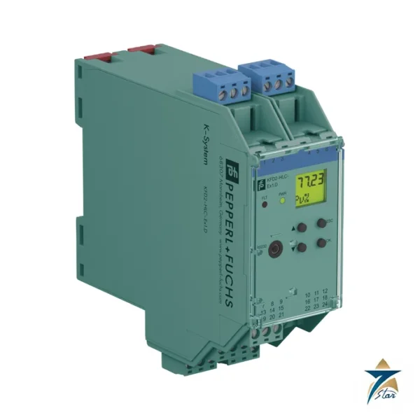
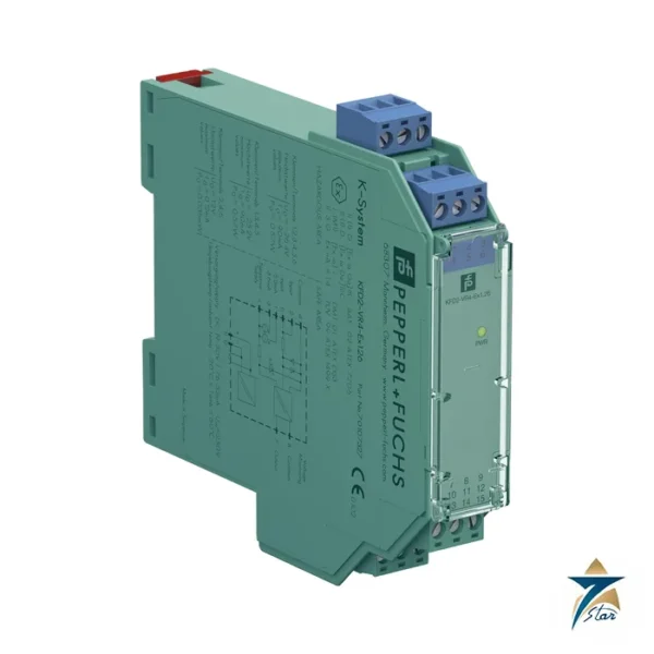
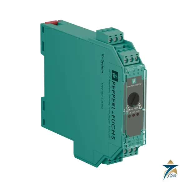
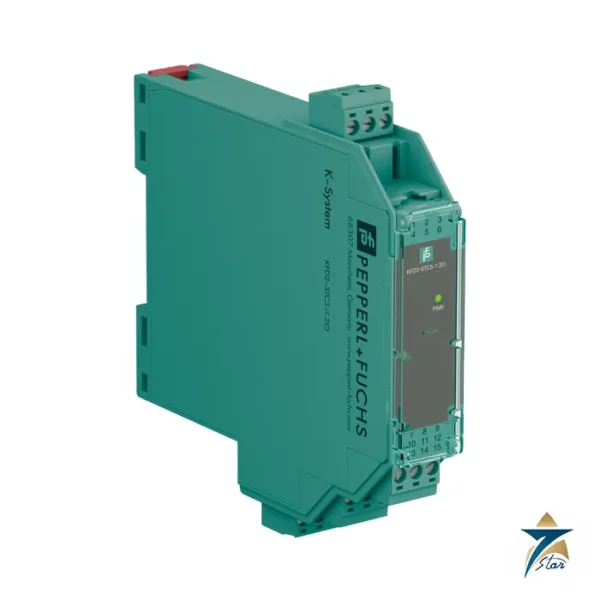
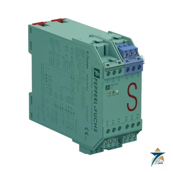
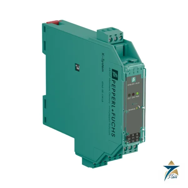
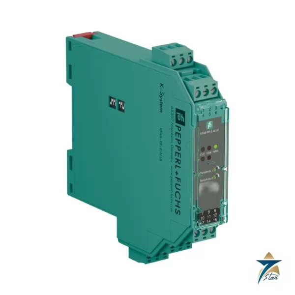
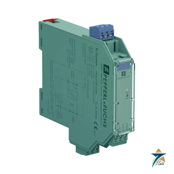
In the part number, KCD2 is the compact 24 V DC range, UT2 the universal temperature converter generation 2 and Ex1 one channel with an Ex ia input. The sibling KFD2-UT2-Ex1 is a 20 mm wide housing with the same function name, and KFD2-GUT-Ex1.D is the larger converter with trip relays and a display.
Seven Star LLC supplies this module in Oman and the GCC as an independent supplier in Muscat.
Technical specifications of the KCD2-UT2-Ex1
| Parameter |
Specification |
| Manufacturer / part number |
Pepperl+Fuchs KCD2-UT2-Ex1 |
| RTD inputs |
Pt10, Pt50, Pt100, Pt500, Pt1000 (EN 60751), GOST Pt types, Cu10, Cu50, Cu100, Ni100; 2-, 3-, 4-wire; lead resistance max. 50 Ω per line |
| Thermocouples |
B, E, J, K, N, R, S, T, L, TXK, TXKH, TXA; internal CJC via KC-CJC-** terminal block or external |
| Other inputs |
Potentiometer 0 to 20 kΩ (2-wire) or 0.8 to 20 kΩ (3-wire); voltage -100 to 100 mV |
| Output |
0 or 4 to 20 mA, source (load 0 to 550 Ω, open circuit ≤ 18 V) or sink mode |
| Fault signal |
Downscale 0 or 2 mA; upscale 21.5 mA (NAMUR NE 43) |
| Accuracy examples |
Pt100: ± (0.06 % of value in K + 0.1 % of span + 0.1 K), 4-wire; mV: ± (50 µV + 0.1 % of span) |
| Reaction time |
mV 1 s; TC with CJC 1.1 s; RTD 3/4-wire 920 ms; 2-wire 800 ms |
| Supply |
19 to 30 V DC, Power Rail or terminals 9+/10-; ≤ 0.98 W |
| Functional safety |
SIL 2 acc. to IEC/EN 61508 / IEC/EN 61511 |
| Hazardous area data |
BASEEFA 13 ATEX 0102 X, [Ex ia Ga] IIC; Uo 9 V, Io 13.1 mA, Po 30 mW; IECEx BAS 13.0057X |
| Ambient temperature |
-20 to 70 °C |
| Housing |
Type A2, 12.5 x 119 x 114 mm, IP20, approx. 100 g |
How the KCD2-UT2-Ex1 is configured and diagnosed
The KCD2-UT2-Ex1 has no keypad. Configuration is done with PACTware through the programming socket: sensor type, wiring, range, damping, output range, fault level and the sink or source mode. The datasheet notes that there is no electrical isolation between the programming input and the supply, so the programming cable itself provides the isolation to avoid ground loops.
Faults such as sensor breakage (all sensors), sensor short-circuit (RTD), or out-of-range readings are shown by an LED and by the user-configured fault indication; on a Power Rail the collective error message is available as well. For thermocouples, internal cold junction compensation needs the removable KC-CJC-** terminal block.
System fit and related parts
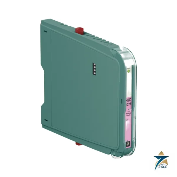
Choose the KCD2-UT2-Ex1 where cabinet space is limited and no local trip contacts are needed. If you need two trip relays and a display, the KFD2-GUT-Ex1.D is the right type; if a 20 mm module is preferred, see the KFD2-UT2-Ex1. The HiC2081 for termination boards is documented together with this family in a shared manufacturer manual.
Selection and ordering checklist
- Sensor type (RTD, TC type, potentiometer or voltage) and wiring.
- Temperature range and output span.
- Source or sink mode for the receiving analog input.
- Cold junction compensation method for thermocouples.
- Ex ia input values: Uo 9 V, Io 13.1 mA, Po 30 mW.
- PACTware and a programming cable for commissioning.
Installation, commissioning and maintenance of the KCD2-UT2-Ex1
Clip the module onto the rail, wire the sensor to terminals 1 to 4 and the output to terminals 5 to 8, then program it. A decade box or calibrator confirms the characteristic at three points. Keep a backup of the PACTware file and the parameter list in the loop folder.
Check accuracy statements against your requirement: the datasheet includes a cold junction fault of about 1.3 K inside the thermocouple figure, so critical thermocouple measurements may need external compensation.
Accuracy and measurement practice with the KCD2-UT2-Ex1
Accuracy figures in the datasheet are given after calibration and include different terms for each sensor type. For a 4-wire Pt100 the error is 0.06 % of the measured value in kelvin plus 0.1 % of span plus 0.1 K; for a thermocouple it is 0.05 % of value in °C plus 0.1 % of span plus about 1.5 K, which includes roughly 1.3 K for cold-junction compensation. A narrow span therefore raises the relative error of the span term, so avoid setting the output span much narrower than the process requires.
Ambient temperature changes shift the result by small amounts per kelvin, and the output is practically independent of supply voltage (under 0.01 % of span) and of load (0.001 % per 100 Ω). Use 3-wire or 4-wire RTD connections for long cable runs, because lead resistance up to 50 Ω per line is allowed but a 2-wire connection adds the cable resistance to the measurement.
Typical applications in Oman and the GCC
Large instrument rooms in refineries, gas plants, power stations and desalination units in Oman use many temperature loops, where 12.5 mm modules such as the KCD2-UT2-Ex1 cut the rack size. The -20 to 70 °C range suits warm control rooms, but check proximity to heat sources.
Family comparison
| Part |
Key difference |
| KCD2-UT2-Ex1 (this part) |
12.5 mm, PACTware only, no relays |
| KFD2-UT2-Ex1 |
20 mm housing, same function name |
| KFD2-GUT-Ex1.D |
40 mm, 2 relays, display |
| HiC2081 |
Termination board version covered by the same manual |
Information to send with an RFQ
- Part number KCD2-UT2-Ex1 and quantity
- Sensor type and range
- Output mode
- Zone and gas group
- Supply method
- Delivery location
Documents and quotation
The manufacturer datasheet for KCD2-UT2-Ex1 is attached on this page, so you can check wiring, approvals and dimensions before ordering. Send the exact part number, quantity and delivery location in Oman or the GCC and Seven Star LLC will reply with a quotation.
Seven Star LLC is an independent supplier in Muscat and is not the manufacturer; confirm availability, lead time and any project approval requirements in your RFQ.



















Reviews
There are no reviews yet.