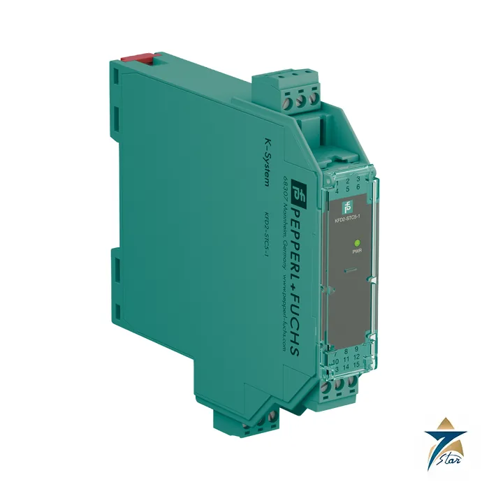
KFD2-STC5-1 SMART transmitter power supply for HART loops
The KFD2-STC5-1 is a single-channel signal conditioner from the Pepperl+Fuchs K-System family. It sits between a 4-20 mA field transmitter and the control system, powers the transmitter from the 24 V DC supply, and passes the measured current on to the controller through a galvanically isolated output. Because digital HART signals are allowed to travel through it in both directions, an asset-management tool or handheld communicator can still talk to the field device while the analog value reaches the DCS or PLC.
Seven Star LLC supplies the KFD2-STC5-1 in Oman and the GCC as an independent supplier in Muscat. The sections below explain what the type code means, which electrical limits matter when sizing a loop, and how the module relates to its two-channel and splitter siblings, so that an RFQ can be written correctly the first time.
Reading the KFD2-STC5-1 type designation
The KFD2-STC5-1 is a type designation of the Pepperl+Fuchs K-System. The datasheet names the function as a SMART transmitter power supply and lists it as a 1-channel signal conditioner with 24 V DC supply through the Power Rail. The two-channel version is the KFD2-STC5-2, and the version with a second, duplicated output for signal splitting is the KFD2-STC5-1.2O. Always match the exact string, because each of these siblings has different terminal assignment and load limits.
The KFD2-STC5-1 is described by the manufacturer as a conditioner for non-hazardous side wiring of 2-wire and 3-wire SMART transmitters and 2-wire SMART current sources. Check the field-side circuit against the datasheet limits rather than assuming a particular approval, because this particular datasheet does not list a hazardous-area certificate for the module itself.
Technical specifications of the KFD2-STC5-1
| Parameter |
Specification |
| Manufacturer / part number |
Pepperl+Fuchs / KFD2-STC5-1 |
| Function |
SMART transmitter power supply, 1 channel, galvanic isolation |
| Supported SMART protocols |
HART, BRAIN, Foxboro |
| Input signal |
4 … 20 mA, 2-wire or 3-wire transmitter, or 2-wire current source |
| Available voltage to transmitter |
≥ 16 V at 20 mA; ≥ 20 V at 4 mA (terminals 1+, 3) |
| Open circuit voltage / short-circuit current |
23 V / 25 mA |
| Output signal |
4 … 20 mA, sink or source mode, overload above 25 mA |
| Output load |
0 … 800 Ω; internal 250 Ω HART resistor on terminal 9 |
| External loop supply (sink mode) |
2 … 30 V DC |
| Supply |
18 … 30 V DC via Power Rail or terminals 14+, 15- |
| Power consumption |
≤ 1.6 W at maximum load; power dissipation ≤ 1 W |
| Accuracy |
Deviation ≤ 10 µA at 20 °C including calibration, linearity and hysteresis |
| Temperature drift |
≤ 0.25 µA/K |
| Bandwidth |
0 … 7.5 kHz (-3 dB) input to output; 0.3 … 7.5 kHz output to input |
| Functional safety |
SIL 2, systematic capability SC 3 (IEC/EN 61508) |
| Isolation |
Input/output and input/supply: basic insulation, 300 V rms (IEC 61010-1) |
| Ambient temperature |
-20 … 70 °C |
| Housing / mounting |
Type B2, 20 x 124 x 115 mm, approx. 200 g, 35 mm DIN rail, IP20, screw terminals |
How the KFD2-STC5-1 conditions a HART loop
A 2-wire transmitter needs a supply voltage and returns its measurement by drawing between 4 and 20 mA from the loop. The KFD2-STC5-1 provides that supply on the field terminals, so no separate loop power supply is required. The current drawn by the transmitter is measured, galvanically separated from the 24 V DC world, and reproduced as a 4-20 mA signal on the control-side terminals. The datasheet states a total deviation of no more than 10 µA at 20 °C, which is the figure to compare with the accuracy budget of the whole measuring chain.
The output is selectable between sink and source behaviour through the way the terminals are wired. In source mode the module drives the current into the controller input; in sink mode an external loop supply of 2 to 30 V DC does the driving and the module regulates the current. When the external voltage exceeds 19 V the datasheet requires a load of at least (V – 19) / 0.02 Ω, and the built-in 250 Ω resistor can serve as that load. HART communication needs a loop resistance of roughly this order, so the same resistor often solves the low-impedance problem of analog input cards.
Digital HART frames are modulated onto the current as a small superimposed signal. The module transfers them in both directions, and test sockets are integrated into the terminals so a handheld communicator can be clipped on without opening the loop. Settling time is 500 µs and rise and fall time 100 µs, which is more than fast enough for the 1200 baud HART carrier.
Where the KFD2-STC5-1 fits in a K-System installation
The module is normally clipped onto a Universal Power Rail, which carries the 24 V DC supply and a collective error line. A power feed module such as the KFD2-EB2 feeds the rail, and the UPR-03 rail section carries the modules. In that arrangement the module takes its supply from the rail and no separate wiring to terminals 14+ and 15- is needed.
Within the family, the KFD2-STC5-2 puts two identical channels in the same 20 mm width, the KFD2-STC5-1.2O adds a second output for a signal split, and the KCD2-STC-1 offers a 12.5 mm wide alternative for tighter cabinets. When the field instrument also needs a trip alarm or a display, the KFD2-CRG2-1.D is the related transmitter supply with relays and scaling.
Selection and ordering checklist for the KFD2-STC5-1
- Confirm that the transmitter is a 2-wire or 3-wire 4-20 mA device or a 2-wire current source, and that its minimum operating voltage is below the 16 V available at 20 mA
- Decide between source and sink mode for the control input and check the controller input resistance against the 0 to 800 Ω load range
- Check whether HART communication must remain available through the module, and size the loop resistance accordingly
- Check the functional-safety requirement: the datasheet lists SIL 2 with systematic capability SC 3
- Confirm the 18 to 30 V DC supply and whether the module will be powered from a Power Rail
- Confirm the cabinet ambient range against -20 to 70 °C
Installation, commissioning and maintenance of the KFD2-STC5-1
Snap the module onto the 35 mm rail or the Power Rail and wire the removable screw terminals. Field wiring goes to terminals 1+, 2- and 3, the control-side wiring to terminals 7 to 9, and the supply to 14+ and 15- when no rail is used. Keep the field cable separated from power cables and use shielded twisted pairs, because the HART carrier is a low-level signal.
Commissioning begins with a loop check: confirm the supply LED, inject 4 mA and 20 mA at the transmitter or simulate with a loop calibrator, and compare the controller reading. Use the integrated test sockets to connect a HART communicator for transmitter configuration; no wiring has to be removed. Under maintenance the module has no adjustable parts, so a fault is cleared by replacing the unit, and keeping one spare per loop type shortens outages.
Typical applications in Oman and the GCC
A 24 V DC powered, isolated 4-20 mA interface of this kind is found wherever field transmitters report to a PLC or DCS: pressure, level and flow measurement on oil and gas gathering stations, process transmitters in power plants, and level and pressure points in desalination and water treatment works. In the Gulf climate the cabinet temperature is often the limiting factor, so the 70 °C upper ambient limit and the 1 W dissipation per channel are worth comparing with the actual enclosure conditions, especially when several modules are mounted side by side.
The galvanic isolation also protects the control cards from ground loops and induced surges on long cable runs between remote instrument shelters and central control rooms, which is a regular situation on large plant sites.
KFD2-STC5-1 and related transmitter power supplies
The table compares the module with siblings from the same datasheet family, using only values stated in the manufacturer documents.
| Part number |
Channels |
Distinguishing feature |
Width |
| KFD2-STC5-1 |
1 |
Single SMART transmitter supply, 4-20 mA output |
20 mm |
| KFD2-STC5-2 |
2 |
Two independent channels |
20 mm |
| KFD2-STC5-1.2O |
1 |
One input, two outputs (signal splitter) |
12.5 mm |
| KCD2-STC-1 |
1 |
Source, sink or 1-5 V output by DIP switch |
12.5 mm |
Information to send with an RFQ for the KFD2-STC5-1
A complete enquiry lets us confirm the right variant and lead time quickly.
- Number of channels and the field transmitter type
- Supply arrangement: Power Rail with a power feed module, or individual terminals
- Required quantity, spare allowance and delivery date
Documents and quotation
The manufacturer datasheet for the KFD2-STC5-1 is attached on this page, so the electrical data, terminal assignment and ambient limits quoted above can be checked against the original document before an order is placed.
Seven Star LLC supplies Pepperl+Fuchs products in Oman and the GCC as an independent supplier in Muscat. Send the quantity, the signal types and the project delivery date, and we will confirm availability and lead time in a written quotation.
Other Models in the Pf Kfd2 Stc5 Range
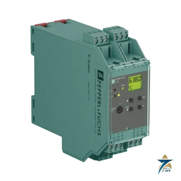
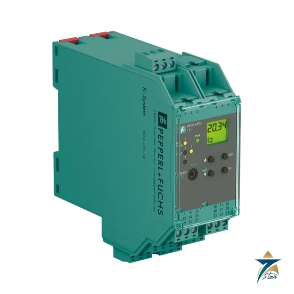
Seven Star LLC supplies models from the Pf Kfd2 Stc5 range in Oman and the GCC. Compare the related models below and request a quote for the one that matches your application.




























Reviews
There are no reviews yet.