Lovato DCRM2 reactive current control relay for capacitor banks
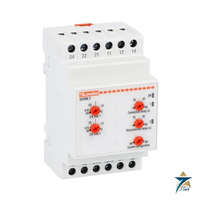
The Lovato DCRM2 is a two-step reactive current control relay, a small power factor controller that switches capacitor steps based on the reactive current measured through a single current transformer. It is a three-module DIN unit with a 380 to 415 V AC auxiliary supply and two changeover relay outputs. Seven Star LLC supplies the DCRM2 in Oman and the GCC as an independent supplier in Muscat.
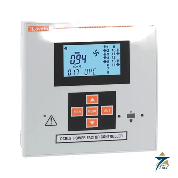
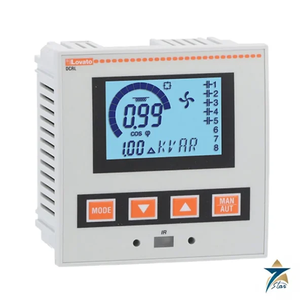
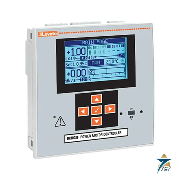
Where larger Lovato controllers such as the DCRL3, DCRL5, DCRL8 or DCRG8 have a bigger display and more steps, the DCRM2 stays deliberately simple, with only the knobs to set the C/K threshold and delay.
DCRM2 technical specifications
| Parameter |
Specification |
| Manufacturer / part number |
Lovato / DCRM2 |
| Function |
Reactive current control relay |
| Auxiliary supply |
380 to 415 V AC, 0.85 to 1.1 Us, 50/60 Hz ±5% |
| Power consumption |
4.4 VA max; 2.4 W max |
| Voltage input |
Rated 480 V AC max; range 80 to 528 V AC; L1-L2 or L-N |
| Current input |
1 input via external CT, up to 5 A; range 0.1 to 6 A |
| Overload |
1.2 Ie constant; 10 In for 1 s; 160 A for 10 ms |
| Adjustments |
C/K for steps 1 and 2: OFF or 0.15 to 2 |
| Connection / disconnection delay |
1 to 60 s |
| System |
Three-phase or single-phase |
| Outputs |
2 changeover relays, 8 A 250 V AC, B300 |
| Insulation |
480 V Ui; 6 kV Uimp |
| Electrical / mechanical life |
100,000 / 30 million operations |
| Operating temperature |
-20 to +60 °C |
| Housing |
3 modules, IP40 front, IP20 terminals; 53.5 x 104.7 x 64.9 mm; 284 g |
How the DCRM2 controls capacitor steps
A capacitor step is switched in when the reactive current needed exceeds the threshold, which is the product of the setting C/K and the current transformer ratio. In practice you calculate C/K from the capacitor step size, the supply voltage and the CT ratio, and then set it separately for step 1 and step 2. The connection and disconnection delay of 1 to 60 s prevents the contactors from hunting when the load fluctuates.
Because it controls by current rather than by displaying power factor, the relay is best on installations with a stable, simple load profile; for variable loads or many steps, a full controller is better.
Where the DCRM2 fits in a capacitor bank
The DCRM2 drives two capacitor contactors in a small bank. The measuring voltage is taken from L1-L2 or L-N and the current from a CT in the remaining phase. Capacitor-duty contactors, protective fuses and discharge resistors complete the bank. For banks with more steps, step up to the DCRL8 or DCRG8.
DCRM2 selection and ordering checklist
- Confirm only two capacitor steps are needed
- Check the auxiliary supply is 380 to 415 V AC
- Choose a current transformer with a 5 A secondary and suitable ratio
- Calculate C/K for each step
- Make sure contactors are capacitor-rated
- Verify enclosure temperature below 60 °C
Installation and commissioning of the DCRM2
Mount it on the DIN rail, wire the voltage reference and CT, and set the delays. A wrong CT polarity or a current taken from the wrong phase relative to the voltage reference is the most common mistake, and it makes the relay add capacitance when it should shed it. Check the sign by observing step behaviour on a known load.
Typical DCRM2 applications in Oman and the GCC
Utility tariffs in several GCC markets penalise low power factor, so small workshops, pump stations and light-industrial buildings fit capacitor banks, and hot sites need the +60 °C operating limit of the relay respected inside the capacitor panel, where the capacitors themselves add heat. A two-step relay is an economical way to fix a stable inductive load.
Practical notes on setting the DCRM2
Start with the simplest sizing: take the kvar of step 1, convert it to current at the supply voltage, divide by the CT ratio and use that as C/K. The same calculation is repeated for step 2. If the relay switches steps too eagerly, raise the delay, and if the power factor still drifts, check that the measured current really includes all the inductive load. A CT installed upstream of a second feeder would see current that the bank cannot correct.
The two relay outputs are rated 8 A at 250 V AC, which is enough for contactor coils, so no interposing relays are normally needed. Keep spare units for capacitor panels that run continuously, because a failed controller leaves the plant paying power factor penalties until it is replaced.
When a bank is first energised, watch the in-rush on the capacitor contactors and confirm that the relay waits for the set delay before the second step connects. Record the final C/K values and delays on the panel documentation. If the site later adds load, remember that the settings were chosen for the original capacitor size and may need to be recalculated.
Information to send with an RFQ for the DCRM2
- Part number DCRM2 and quantity
- Supply voltage and frequency
- Capacitor step sizes in kvar
- CT ratio
- Panel temperature
- Delivery location
Site conditions in Oman for the DCRM2
Control cabinets in Gulf plants often run hot, because many sit in outdoor kiosks or in rooms where air conditioning is not always reliable. Before you finalise the DCRM2, check the permitted ambient range and any derating stated by the manufacturer against the real temperature inside your panel, and leave the recommended spacing around the device so that heat can escape. Long cable runs between the field and the marshalling cabinet are common on large sites, so confirm the signal types, wiring limits and earthing arrangement early in the design.
It also helps to standardise on a small number of part numbers across a project. Keeping a few spare DCRM2 units on site in Oman shortens recovery time after a fault, and documenting configuration settings makes replacement faster for the maintenance team.
Documents and quotation
Send the part number DCRM2 and we will confirm the documents available for it, such as the technical data sheet, wiring diagram and instruction sheet, together with availability and lead time.
Seven Star LLC is an independent supplier in Muscat and is not an official channel of the manufacturer. Share the quantity, delivery location and project reference with the request and we will answer with a formal quotation.























Reviews
There are no reviews yet.