
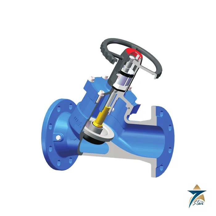
The Weflo Fig. 1209 is a flanged ductile iron balancing valve for hydronic heating and chilled water systems, designed to set and verify the flow in each branch of a circuit during commissioning. It has an inside-screw, non-rising stem, an EPDM-coated disc, a back-seating feature and two test points on each valve, so commissioning engineers can measure differential pressure and read the flow from the manufacturer flow charts. The Weflo Fig. 1209 is rated at 16 bar (250 psi) in sizes DN50 to DN300, and the grooved-end Fig. 1210 shares the same internal design for grooved pipework.
Seven Star LLC supplies the Weflo Fig. 1209 and Fig. 1210 to MEP contractors, testing and commissioning specialists and facility managers in Oman and the GCC, with engineering support in Muscat. For consultants searching for a chilled water balancing valve or a commissioning set from a valves supplier in Oman, the Weflo Fig. 1209 offers a documented, flanged solution for main and branch pipework.
A balancing valve introduces an adjustable, measurable resistance into a pipe so that flow can be divided correctly between parallel circuits. Without balancing, water takes the path of least resistance: coils close to the pump receive too much flow and remote coils receive too little, which leads to poor comfort and wasted pump energy. By throttling the disc of the Weflo Fig. 1209, the commissioning engineer raises the resistance in over-supplied branches until every terminal receives its design flow rate.
The two test points allow a differential pressure meter to be connected across the valve. With the handwheel set at a known position, the measured pressure difference is converted to flow using the Weflo flow charts, which is what the datasheet means when it says the valve can be set in conjunction with flow charts. As general background, UK practice often calls valves of this kind commissioning valves or double regulating valves; buyers who need a specific memory-stop arrangement should confirm that detail with Seven Star LLC before ordering, as it is not described on the datasheet.
The body, bonnet and handwheel of the Weflo Fig. 1209 are ductile iron to EN 1563 EN-GJS-450-10 (ASTM A536 Grade 65-45-12). The disc is EPDM-encapsulated ductile iron, the disc nut is brass CuZn39Pb1 (ASTM B124 C37700), the stem is stainless steel X20Cr13 (ASTM A276 Type 420), and O-rings and the bonnet gasket are EPDM. Interior and exterior surfaces are protected with fusion bonded coating.
Flanges and drilling comply with EN 1092-2 PN10/16 and ANSI B16.1 Class 125, and the face-to-face dimension follows EN 558-1 basic series 1, so the Fig. 1209 drops into standard globe-valve spaces. Weflo publishes lengths from 230 mm at DN50 to 850 mm at DN300, with handwheel diameters of 205 mm on the smaller sizes rising to 450 mm on DN250 and DN300. The Fig. 1210 grooved version is listed with outside diameters from 60.3 mm to 323.9 mm to suit grooved steel pipe. Higher ratings of 20 bar, 25 bar or 300 psi are available as an option.
The Weflo Fig. 1209 datasheet lists the following design features.
The Weflo Fig. 1209 belongs on the larger pipework of a hydronic system: chiller and boiler primary circuits, secondary distribution headers, riser branches serving individual floors, and the connections to air handling units and large fan coil groups. In the Gulf climate, where chilled water plants run for most of the year, correct balancing has a direct effect on chiller efficiency and pump energy, which is why consultants on hospitals, malls, government buildings and hotel projects in Muscat and across the GCC specify measurable balancing valves on each main branch.
Seven Star LLC supplies the Weflo Fig. 1209 for new installations and for re-balancing of existing plants in Oman, including commercial and industrial sites in Sohar and Salalah. It is frequently used together with variable speed pumps such as the Grundfos MAGNA3 circulator, with pressure independent valves such as the Danfoss AB-QM PICV at terminal units, and with electronic flow control such as the Belimo Energy Valve where energy metering is also required.
Weflo Fig. 1209 data below is from the Weflo datasheet for Fig. 1209 and Fig. 1210.
| Parameter | Specification |
|---|---|
| Model | Weflo Fig. 1209 (flanged) / Fig. 1210 (grooved) Balancing Valve |
| Size range | DN50 to DN300 |
| Rated working pressure | 16 bar / 250 psi (20 bar, 25 bar, 300 psi optional) |
| Stem design | Inside screw, non-rising stem, back seating |
| Measurement | Two test points per valve; setting with Weflo flow charts |
| Flanges | EN 1092-2 PN10/16, ANSI B16.1 Class 125 |
| Face-to-face | EN 558-1 basic series 1; 230 mm (DN50) to 850 mm (DN300) |
| Body, bonnet, handwheel | Ductile iron EN-GJS-450-10 / A536 65-45-12 |
| Disc | EPDM encapsulated ductile iron |
| Stem | Stainless steel X20Cr13 / A276 Type 420 |
| Disc nut | Brass CuZn39Pb1 / B124 C37700 |
| O-ring and gasket | EPDM |
| Corrosion protection | Fusion bonded coating, interior and exterior |
| Grooved version OD | Fig. 1210: 60.3 mm to 323.9 mm |
This section gives general engineering guidance for balancing valves and is not a Weflo instruction. Size a balancing valve for its design flow rather than simply matching the pipe size; a valve that is too large will be set almost closed, where accuracy and resolution are poorest. Straight pipe runs upstream and downstream of the valve, typically several pipe diameters, improve the repeatability of differential pressure readings, and the test points should be positioned so that a meter can be connected easily after insulation is applied.
Keep a record of the final handwheel setting and measured flow for each Weflo Fig. 1209 in the commissioning report, so that the valve can be returned to its design setting after maintenance. Seven Star LLC can supply the Weflo flow chart data with the order to support the testing and commissioning team.
To request a quotation for the Weflo Fig. 1209 or the grooved Fig. 1210, send Seven Star LLC your sizes, design flow rates, pressure rating and end connections. Our engineering team in Muscat can confirm availability and lead time, provide the Weflo technical datasheet available for download on this page, and assist with selection for chilled water and heating projects in Oman and the GCC.
Choose the option that best fits your needs to get the fastest response from our team.
Automatically fill the RFQ form with this product's details for a faster process.
Manually enter multiple part numbers, specific brands, or custom requirements.











Reviews
There are no reviews yet.