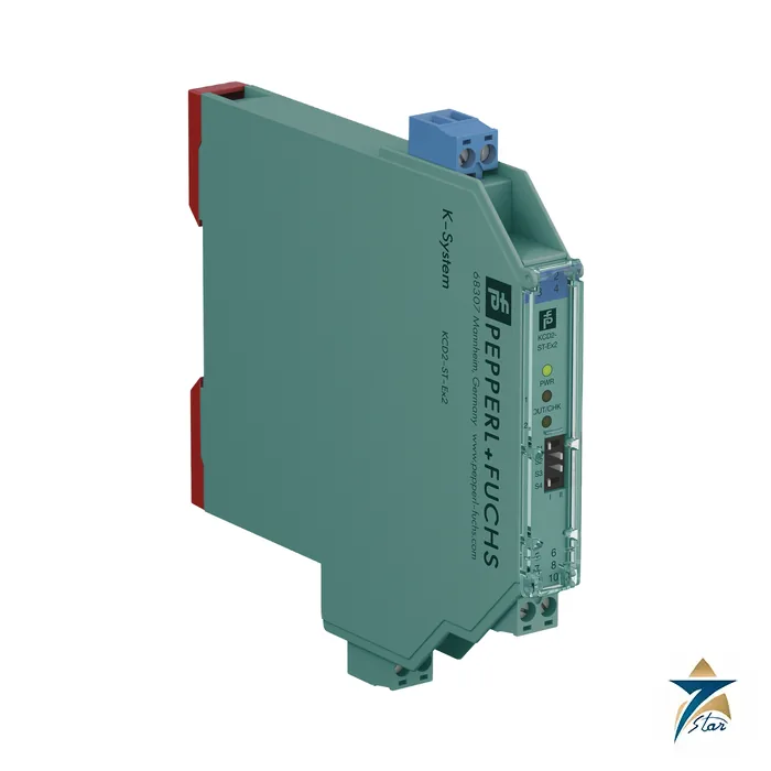
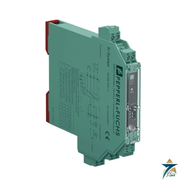
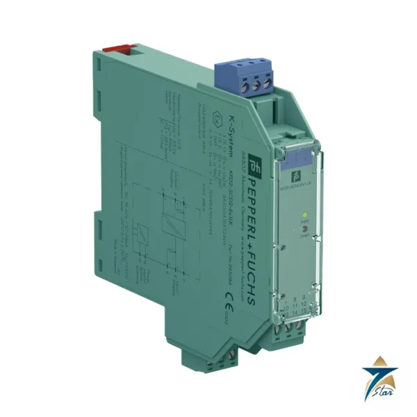
KCD2-ST-Ex2 two-channel switch amplifier in a 12.5 mm housing
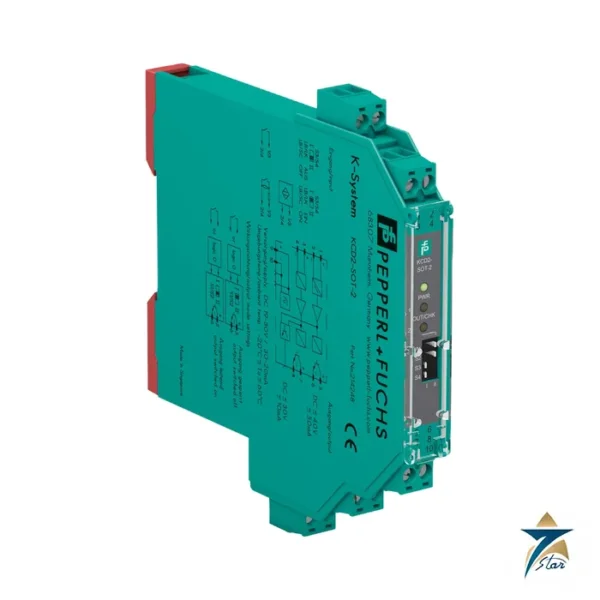
The KCD2-ST-Ex2 is a two-channel isolated switch amplifier from the Pepperl+Fuchs K-System. It takes the on/off state of NAMUR proximity sensors or dry contacts located in a hazardous area and passes it to the safe area, where each channel controls its own active transistor output. The housing is only 12.5 mm wide, so two inputs occupy very little rail space.
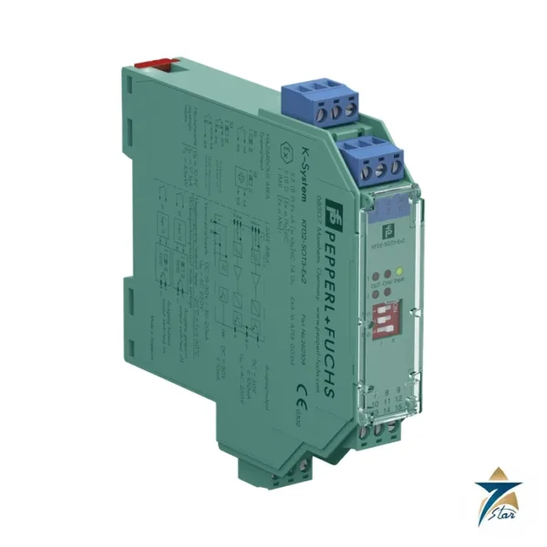
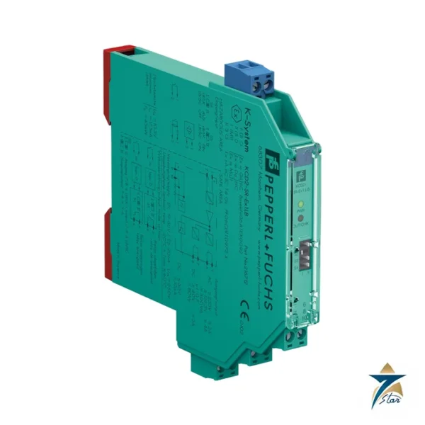
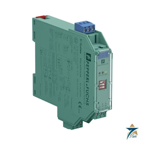
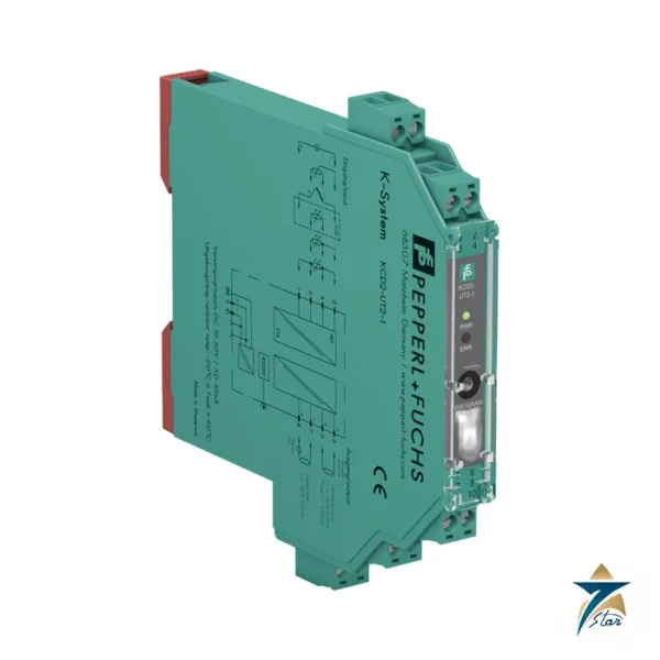
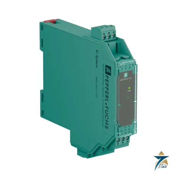
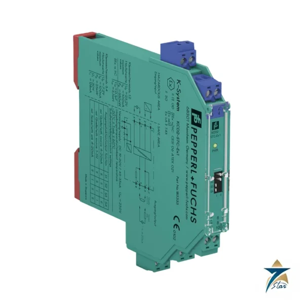
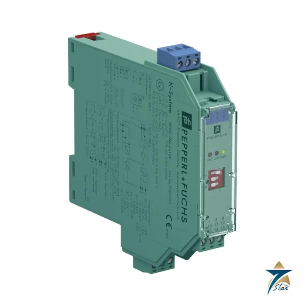
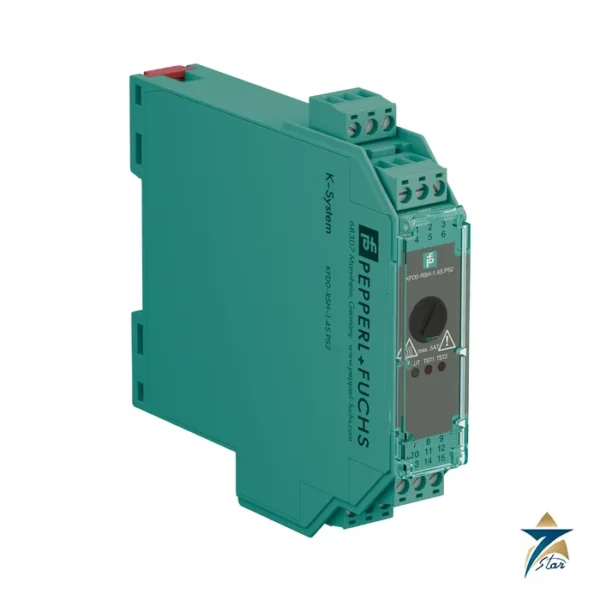
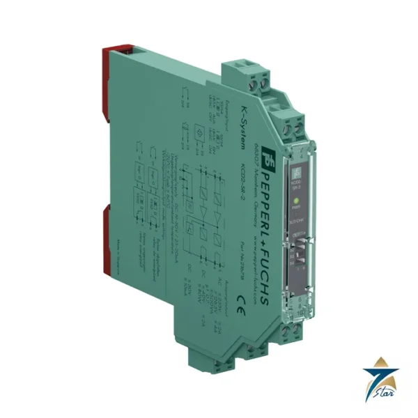
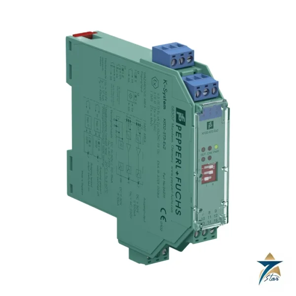
In the part number, KCD2 is the compact 24 V DC range, ST means switch amplifier with transistor outputs, and Ex2 means two channels with an Ex ia input. The relay version is KCD2-SR-Ex1.LB, and the 20 mm transistor versions are KFD2-ST3-Ex2 and KFD2-SOT3-Ex2.
Seven Star LLC supplies this module in Oman and the GCC as an independent supplier in Muscat.
Technical specifications of the KCD2-ST-Ex2
| Parameter |
Specification |
| Manufacturer / part number |
Pepperl+Fuchs KCD2-ST-Ex2 |
| Channels |
2 inputs, terminals 1+/2- and 3+/4-; 2 transistor outputs, terminals 5 and 6 |
| Input |
NAMUR acc. to EN 60947-5-6 or dry contact; open circuit approx. 10 V DC, short-circuit current approx. 8 mA |
| Switching point / hysteresis |
1.2 to 2.1 mA / approx. 0.2 mA |
| Line fault detection |
Breakage ≤ 0.1 mA; short-circuit ≥ 6.5 mA; can be switched off by DIP switch |
| Output |
Active transistor, rated 30 V DC / 50 mA; 1-signal = supply voltage minus 3 V at 50 mA; 0-signal blocked, off-state current ≤ 10 µA |
| Response / frequency |
Response time ≤ 200 µs; switching frequency ≤ 5 kHz; pulse and pause min. 100 µs |
| Supply |
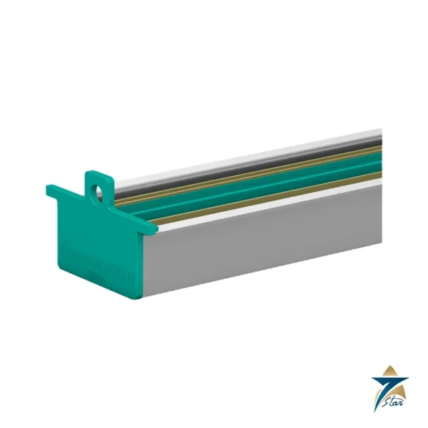
19 to 30 V DC, terminals 9+/10- or Power Rail; power dissipation ≤ 800 mW including the output |
| Functional safety |
SIL 2, systematic capability SC 3 |
| Hazardous area data |
BASEEFA 13 ATEX 0080, [Ex ia Ga] IIC, [Ex ia Da] IIIC, [Ex ia Ma] I; Uo 10.5 V, Io 17.1 mA, Po 45 mW; IECEx BAS 13.0046 |
| Isolation |
Input to output and input to supply: reinforced insulation, 300 V rms; outputs share common pole 9+ |
| Ambient temperature |
-20 to 60 °C; up to 70 °C with the mounting conditions in the manual |
| Housing |
Type A2, 12.5 x 119 x 114 mm, IP20, approx. 100 g |
How the KCD2-ST-Ex2 switches and signals faults
Each input circuit supplies a NAMUR sensor and watches the current. Below about 1.2 mA the sensor is read as open, above about 2.1 mA as closed, with 0.2 mA of hysteresis. A current under 0.1 mA means a broken line and a current above 6.5 mA means a short-circuit. Switches on the front choose the normal or reversed action for each channel and allow line fault detection to be turned off, which is needed with plain dry contacts that carry no resistor network.
A fault is shown on the LEDs according to NAMUR NE 44 and sent to a collective error output on the Power Rail. Because the transistor outputs are active and share the supply common, they suit PLC digital inputs rather than isolated load switching.
System fit and related parts
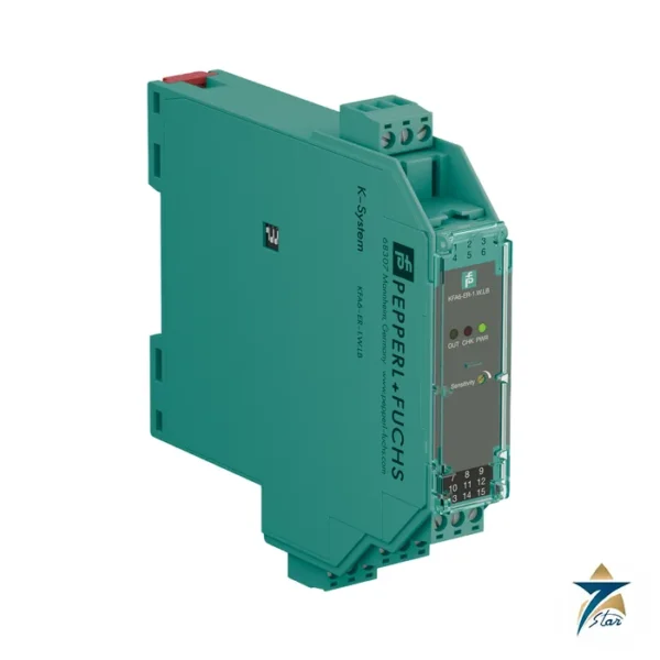
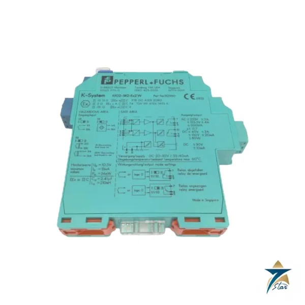
Choose the KCD2-ST-Ex2 when the receiving device accepts a 24 V DC logic signal and rack space matters. If you need potential-free contacts, choose the KCD2-SR-Ex1.LB or KFD2-SR2-Ex2.W relay modules. If each channel must be galvanically separate at the output, the KFD2-ST3-Ex2 is a better match. For passive outputs use KFD2-SOT3-Ex2.
Selection and ordering checklist
- Sensor type: NAMUR proximity or dry contact with resistor network (400 Ω to 2 kΩ series, 10 kΩ parallel).
- Normal or reversed action for each channel.
- Receiving input voltage within 19 to 30 V DC minus 3 V.
- Ex ia entity values: Uo 10.5 V, Io 17.1 mA, Po 45 mW.
- Power Rail or terminal supply.
- Maximum switching frequency required, up to 5 kHz.
Installation, commissioning and maintenance of the KCD2-ST-Ex2
Clip the module on the rail, set the DIP switches for mode and line fault detection before power-up, wire the sensors to terminals 1 to 4, and connect outputs 5 and 6 to the control inputs. Operate each sensor and check that the matching LED and PLC input follow. Disconnect each field cable once to confirm that line fault detection reaches the collective error output.
No scheduled adjustment is needed. In dusty sites inspect the clear front cover and terminals, and keep a spare module on the shelf for fast change-out.
Using dry contacts with the KCD2-ST-Ex2
A plain mechanical contact looks like a permanent short or open circuit unless a resistor network is placed at the contact. The datasheet wiring diagram uses a 10 kΩ resistor in parallel and a resistor between 400 Ω and 2 kΩ in series, which keeps the current in the NAMUR window and keeps line fault detection valid. Without this network, switch line fault detection off on that channel.
Contacts in Zone 1 or Zone 2 must be classified as simple apparatus or otherwise approved; check the field device certificate together with the entity values of the barrier.
Typical applications in Oman and the GCC
The KCD2-ST-Ex2 is used for valve position limit switches, pump status contacts, level switches and proximity sensors on skids at oil, gas, power and desalination sites. High density marshalling cabinets in Oman benefit from the narrow housing, but keep an eye on cabinet temperature.
Family comparison
| Part |
Key difference |
| KCD2-ST-Ex2 (this part) |
2 channels, active transistor outputs, 12.5 mm |
| KCD2-SR-Ex1.LB |
1 channel, relay output, 12.5 mm |
| KFD2-ST3-Ex2 |
2 channels, 20 mm, transistor |
| KFD2-SR2-Ex2.W |
2 channels, relay outputs, 20 mm |
Information to send with an RFQ
- Part number KCD2-ST-Ex2 and quantity
- Sensor type
- Required action (normal or reversed)
- Zone and gas group
- Supply method
- Delivery location
Documents and quotation
The manufacturer datasheet for KCD2-ST-Ex2 is attached on this page, so you can check wiring, approvals and dimensions before ordering. Send the exact part number, quantity and delivery location in Oman or the GCC and Seven Star LLC will reply with a quotation.
Seven Star LLC is an independent supplier in Muscat and is not the manufacturer; confirm availability, lead time and any project approval requirements in your RFQ.



















Reviews
There are no reviews yet.