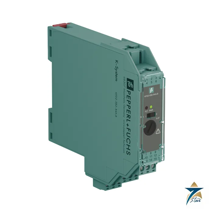
KFD2-EB2.R4A.B redundant power feed module for the Power Rail
The KFD2-EB2.R4A.B feeds 24 V DC into the Power Rail that supplies K-System isolators, with a maximum of 4 A and a replaceable 5 AT fuse. It is designed for redundant power: two modules are used, each wired to its own supply, and either can carry the rail alone.
It also contains a collective error relay that alerts the controller when any isolator on the rail has a device or wiring fault. In the code, EB2 is the power feed module generation, R4A the 4 A redundant version and B a revision with reversible relay contact. Its sibling KFD2-EB2 has a simpler function.
Seven Star LLC supplies this module in Oman and the GCC as an independent supplier in Muscat.
Technical specifications of the KFD2-EB2.R4A.B
| Parameter |
Specification |
| Manufacturer / part number |
Pepperl+Fuchs KFD2-EB2.R4A.B |
| Supply |
20 to 30 V DC at terminals 11+/12- and 8+/9-; do not exceed rated voltage of plugged devices |
| Fuse |
5 AT / 250 V AC, replaceable; use max. 80 % of rating |
| Output |
Power Rail, max. 4 A; output voltage Ur = Ui – 0.6 V |
| Fault relay |
NO contact (reversible by DIP switch): 30 V AC / 2 A (cos φ ≥ 0.7), 40 V DC / 2 A; delay approx. 20 ms |
| Indicators |
Green LED power, red LED fault |
| Bus |
Rail bus forwarded to terminals 13 and 15 for RS-485 of KFD2-WAC2-Ex1.D; terminal 14 for test |
| Power dissipation |
≤ 2.4 W |
| Functional safety |
No dangerous failures; safe state of supplied isolators is the de-energized state |
| Hazardous area data |
UL 22 ATEX 2853 X, Ex ec nC IIC T4 Gc, Zone 2 / Div. 2 |
| Ambient temperature |
-40 to 60 °C; up to 70 °C with manual mounting conditions |
| Housing |
Type B2, 20 x 119 x 115 mm, IP20, approx. 100 g |
How the KFD2-EB2.R4A.B keeps the rail alive
Two KFD2-EB2.R4A.B modules are fitted on the same Power Rail, each connected to an independent 24 V supply. If one supply or module fails, the other continues feeding the rail without interruption. The collective error relay switches on module fault, supply fault or any isolator fault reported over the rail.
The relay output can be set normally open or normally closed, so the alarm logic can be chosen to match the controller. A replaceable fuse provides group fusing for all devices on the rail.
System fit and related parts
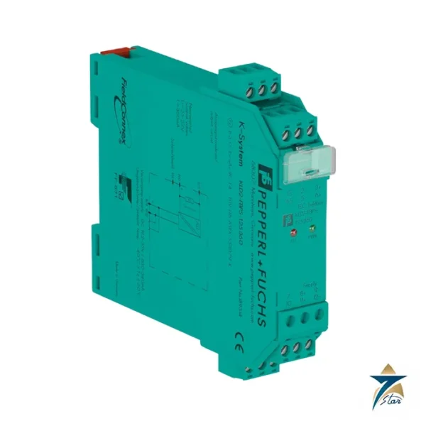
Use the KFD2-EB2.R4A.B with Power Rail-compatible K-System modules such as KFD2-STC5-1, KFD2-UT2-Ex1 and KCD2-ST-Ex2. The non-redundant sibling KFD2-EB2 feeds the same rail from a single supply. The UPR-03 rail itself is a separate part, and the manufacturer notes that redundant systems need two feed modules.
Selection and ordering checklist for the KFD2-EB2.R4A.B
- Redundancy: order two modules per rail.
- Total rail current below 4 A.
- Independent supplies, each 20 to 30 V DC.
- Fault relay logic: NO or NC.
- Spare 5 AT fuses.
- Optional RS-485 bus for a KFD2-WAC2-Ex1.D.
Installation, commissioning and maintenance of the KFD2-EB2.R4A.B
Fit the two modules at the ends or as specified in the rail layout, wire each to its own supply, set the relay mode by DIP switch and test by switching off one supply. Confirm that the fault relay signal reaches the controller.
Keep spare fuses and check the fuse state when the red LED is on. Do not exceed the 80 % fuse loading.
Test the alarm path during commissioning by pulling one isolator from the rail and by switching off one supply at a time. Record the relay contact state in each case so the control room operators know what the alarm means when it appears.
Power budget of the rail fed by the KFD2-EB2.R4A.B
Add the supply currents of every module on the rail and compare the total against 4 A with margin. Remember that the KFD2-EB2.R4A.B drops about 0.6 V between its supply and the rail, and that its voltage must not exceed the rated voltage of any plugged-in device.
In redundant use each module should be able to carry the full load, and two supplies on separate circuits protect against loss of one feeder. Where a plant has a UPS and a mains-fed 24 V supply, feeding one module from each gives protection against a failed power supply as well as a failed feeder breaker.
Typical applications in Oman and the GCC
In Oman and the GCC the KFD2-EB2.R4A.B is used in control room marshalling cabinets of oil, gas and power plants, where loss of the 24 V supply for dozens of isolators would shut down a unit.
Family comparison
| Part |
Key difference |
| KFD2-EB2.R4A.B (this part) |
Redundant feed, 4 A, reversible fault relay |
| KFD2-EB2 |
Power feed module, single supply |
| UPR-03 |
Power Rail |
| KFD2-WAC2-Ex1.D |
Device using the rail RS-485 bus |
Information to send with an RFQ
- Part number KFD2-EB2.R4A.B and quantity (two per redundant rail)
- Total rail current
- Supply voltage
- Fault relay mode
- Delivery location
Site conditions in Oman for the KFD2-EB2.R4A.B
Electrical rooms and outdoor panels in the Gulf often operate well above the 25 °C reference temperature used in many catalogues. Before you finalise the KFD2-EB2.R4A.B, compare the expected panel temperature with the operating range and any output derating stated in the manufacturer documentation, and leave the recommended clearance above and below the device for convection. Supply quality also varies between sites, so confirm the input voltage range, frequency and any requirements for protection on the supply side.
Where the device feeds or monitors critical loads, plan how faults will be signalled to the control system and how a replacement can be installed quickly. Keeping one spare KFD2-EB2.R4A.B per site and recording its settings helps maintenance teams in Oman restore service with minimum downtime.
Documents and quotation
The manufacturer datasheet for KFD2-EB2.R4A.B is attached on this page, so you can check wiring, approvals and dimensions before ordering. Send the exact part number, quantity and delivery location in Oman or the GCC and Seven Star LLC will reply with a quotation.
Seven Star LLC is an independent supplier in Muscat and is not the manufacturer; confirm availability, lead time and any project approval requirements in your RFQ.











Reviews
There are no reviews yet.