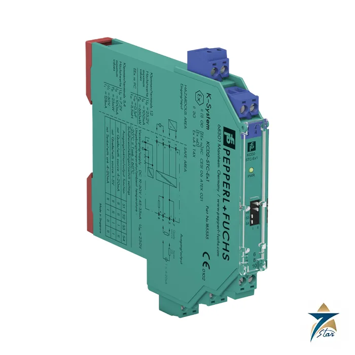
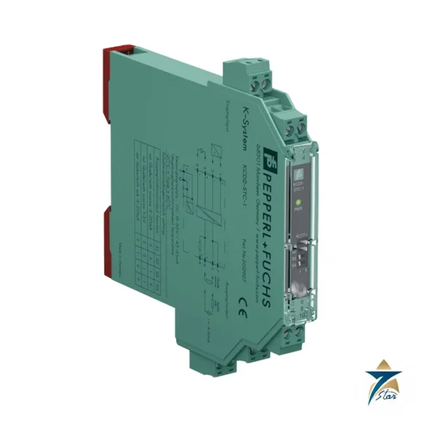
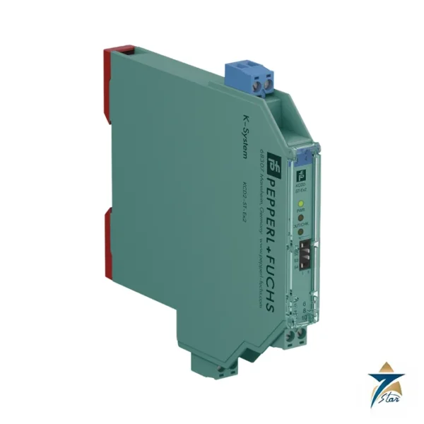
KCD2-STC-Ex1 SMART transmitter power supply in 12.5 mm
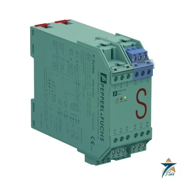
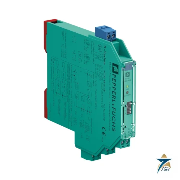
The KCD2-STC-Ex1 is a single-channel isolated barrier that supplies a 2-wire SMART transmitter in a hazardous area and returns the 4 to 20 mA signal to the safe area. It also accepts 2-wire SMART current sources, passes HART or BRAIN digital signals in both directions, and fits into a 12.5 mm housing of the Pepperl+Fuchs KC-System.
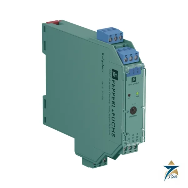
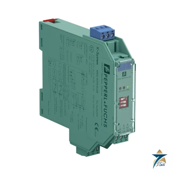
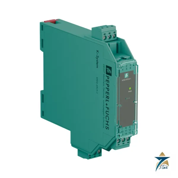
Part number reading: KCD2 is the compact 24 V DC range, STC the SMART transmitter power supply, and Ex1 one channel. The related KFD2-STC5-1 and KCD2-STC-1 are other transmitter power supplies; confirm exact variants against the hazardous-area approval before substituting.
Seven Star LLC supplies the module in Oman and the GCC as an independent supplier in Muscat.
Technical specifications of the KCD2-STC-Ex1
| Parameter |
Specification |
| Manufacturer / part number |
Pepperl+Fuchs KCD2-STC-Ex1 |
| Input |
2-wire SMART transmitter or current source, 4 to 20 mA limited to about 26 mA; terminals 1+, 2- and 3+, 4- |
| Available voltage at transmitter |
≥ 15 V at 20 mA, ≥ 18 V at 4 mA; open circuit 22 V / 26 mA |
| Output |
4 to 20 mA source (load 0 to 350 Ω), 4 to 20 mA sink (10 to 30 V), or 1 to 5 V via internal 250 Ω resistor |
| Accuracy |
< 0.1 % of full scale for current, ≤ ± 0.2 % for 1 to 5 V |
| Temperature drift |
< 2 µA/K (-20 to 70 °C) |
| Bandwidth / settling |
0 to 3 kHz (-3 dB) both directions / ≤ 50 ms |
| Supply |
19 to 30 V DC, Power Rail or terminals 9+/10-; ≤ 45 mA, ≤ 800 mW |
| Protocols |
HART, BRAIN |
| Functional safety |
SIL 2, SC 3 acc. to IEC/EN 61508 |
| Hazardous area data |
CESI 06 ATEX 021 X, [Ex ia Ga] IIC; Uo 25.2 V, Io 100 mA, Po 630 mW, Ci 5.7 nF; supply side CESI 19 ATEX 021 X, II 3G Ex ec IIC T4 Gc |
| Ambient temperature |
-40 to 70 °C |
| Housing |
Type A2, 12.5 x 119 x 114 mm, IP20, approx. 100 g |
How the KCD2-STC-Ex1 powers and isolates the loop
Terminals 1+ and 2- of the KCD2-STC-Ex1 deliver the loop supply and read the transmitter current. The transmitter has at least 15 V available at 20 mA, so the maximum loop resistance (cable, barrier drop and any indicator) must leave enough voltage for the device. The signal is transferred across galvanic isolation and re-created at the output.
Output mode is chosen by DIP switches: source mode, where the module drives the current into a load of up to 350 Ω; sink mode, where the control system supplies 10 to 30 V; or a 1 to 5 V output across an internal 250 Ω resistor. If the HART communication resistance in the loop is too small, the internal 250 Ω between terminals 6 and 8 can be used, and the terminals include test sockets for a HART communicator.
System fit and related parts
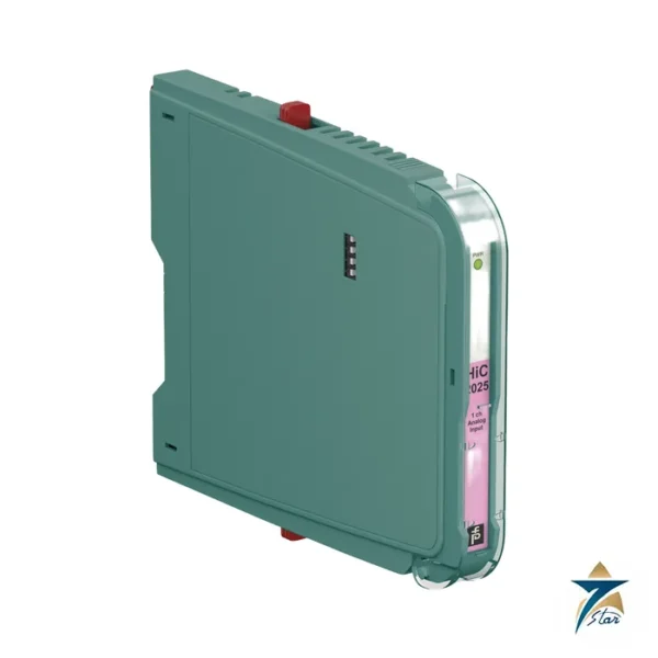
The KCD2-STC-Ex1 sits between a Zone 0, 1 or 2 transmitter (pressure, level, temperature) and an analog input card or an HART multiplexer. Check the sensor entity parameters first: the output is limited to Uo 25.2 V and Io 100 mA. For more loops per rack with 20 mm housing, the KFD2-STC5-1 and KFD2-STC5-2 are alternatives, and HiC2025 is the same function as a plug-in module for a termination board.
Selection and ordering checklist
- Confirm 2-wire transmitter (not 3-wire or 4-wire) and its minimum supply voltage.
- Calculate loop voltage: 15 V available at 20 mA minus cable drop.
- Choose source, sink or 1 to 5 V output for the receiving input.
- Check HART loop resistance; use the internal 250 Ω if needed.
- Check intrinsic safety entity values of transmitter and cable.
- Verify 19 to 30 V DC supply or Power Rail.
Installation, commissioning and maintenance of the KCD2-STC-Ex1
Clip the module onto the DIN rail, set the DIP switches before powering up and wire the blue field terminals separately from the safe-area terminals. Inject 4, 12 and 20 mA with a loop calibrator and check the output at the control side; connect a HART communicator to the test sockets to confirm digital communication.
The module does not need calibration in service. When replacing a failed barrier, keep the DIP switch positions and loop documentation identical, and re-run a loop check.
Typical applications in Oman and the GCC
The KCD2-STC-Ex1 is common for pressure and level transmitters on separators, tanks and compressors at oil and gas sites in Oman, and for temperature and flow transmitters on gas turbine and desalination utilities. The 70 °C upper limit helps in warm field enclosures but should be derated against actual cabinet temperature.
Family comparison
| Part |
Key difference |
| KCD2-STC-Ex1 (this part) |
12.5 mm, 1 channel, SMART supply, source or sink or 1 to 5 V |
| KFD2-STC5-1 |
20 mm housing, 1 channel SMART supply |
| KFD2-STC5-2 |
20 mm housing, 2 channels |
| HiC2025 |
12.5 mm plug-in module for a HiC termination board, SMART supply |
Information to send with an RFQ
- Part number KCD2-STC-Ex1 and quantity
- Transmitter model and Ex data
- Required output mode
- HART use yes or no
- Supply method
- Delivery location
Site conditions in Oman for the KCD2-STC-Ex1
Control cabinets in Gulf plants often run hot, because many sit in outdoor kiosks or in rooms where air conditioning is not always reliable. Before you finalise the KCD2-STC-Ex1, check the permitted ambient range and any derating stated by the manufacturer against the real temperature inside your panel, and leave the recommended spacing around the device so that heat can escape. Long cable runs between the field and the marshalling cabinet are common on large sites, so confirm the signal types, wiring limits and earthing arrangement early in the design.
It also helps to standardise on a small number of part numbers across a project. Keeping a few spare KCD2-STC-Ex1 units on site in Oman shortens recovery time after a fault, and documenting configuration settings makes replacement faster for the maintenance team.
Documents and quotation
The manufacturer datasheet for KCD2-STC-Ex1 is attached on this page, so you can check wiring, approvals and dimensions before ordering. Send the exact part number, quantity and delivery location in Oman or the GCC and Seven Star LLC will reply with a quotation.
Seven Star LLC is an independent supplier in Muscat and is not the manufacturer; confirm availability, lead time and any project approval requirements in your RFQ.



















Reviews
There are no reviews yet.