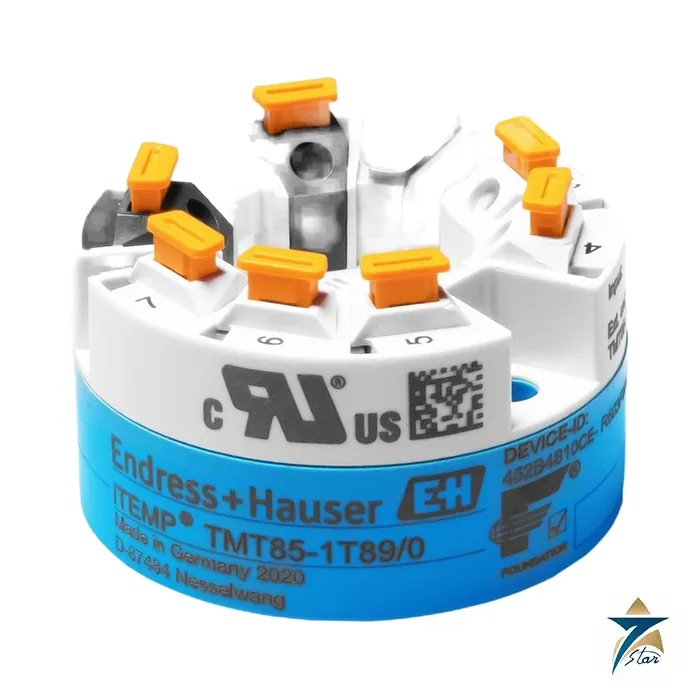
TMT85 iTEMP dual-input FOUNDATION Fieldbus head transmitter
The Endress+Hauser TMT85 is a two-wire head transmitter from the iTEMP family that converts the signal of one or two temperature sensors into a digital FOUNDATION Fieldbus H1 value. It is built for terminal head form B (flat face) to DIN EN 50446, so it drops into the same head as a classic 4–20 mA transmitter but speaks fieldbus on the segment instead of an analog loop. Seven Star LLC supplies the TMT85 in Oman and the GCC as an independent supplier based in Muscat.
Two universal sensor inputs are the headline feature. Each input accepts an RTD, a thermocouple, a resistance value or a millivolt signal, and the combination of two sensors unlocks redundancy and drift-monitoring functions that a single-channel transmitter cannot offer. The device is powered directly from the fieldbus, supports FISCO/FNICO segments and can be used as intrinsically safe equipment up to Zone 1 when the correct approval version is ordered.
There is no long ordering code table in the technical information for this model; the exact feature set (approvals, terminals, housing) is defined when the unit is configured, so always quote the full order code from the nameplate of the unit being replaced.
TMT85 technical specifications
| Parameter |
Specification |
| Manufacturer / part number |
Endress+Hauser iTEMP TMT85 |
| Type |
Two-wire head transmitter, terminal head form B (flat face) to DIN EN 50446 |
| Sensor inputs |
2 independent inputs: RTD, thermocouple, resistance (10 to 400 Ω or 10 to 2,000 Ω), voltage (–20 to 100 mV) |
| Output / protocol |
FOUNDATION Fieldbus H1, IEC 61158-2, 31.25 kBit/s, Manchester II coding; FISCO/FNICO to IEC 60079-27 |
| Supply voltage |
9 to 32 V DC via the bus, polarity-independent (maximum 35 V); FISCO/FNICO segments 9 to 17.5 V DC |
| Current consumption |
≤ 11 mA |
| Galvanic isolation |
2 kV AC for 1 minute (input/output); the two sensor inputs are not isolated from each other |
| Response time / switch-on delay |
1 s per channel / 8 s |
| Typical accuracy |
Pt100, 0 to 200 °C: 0.08 °C typical; Pt100 formula 0.06 °C + 0.006 % x (MV – LRV) |
| Ambient temperature |
–40 to 85 °C; storage –40 to 100 °C; humidity up to 95 % with condensation permitted |
| Degree of protection |
IP 20 as a bare head transmitter; IP 66/67 when installed in TA30A, TA30D or TA30H field housing |
| Vibration |
10 to 2,000 Hz at 5 g |
| Weight / housing |
Approx. 40 to 50 g; polycarbonate housing, PU potting |
| Function blocks |
3 Analog Input blocks per channel (2 x 3 AI), 1 PID, 1 Input Selector |
All values above come from the manufacturer technical information. Hazardous-area limits for ambient temperature differ by approval and are given in the separate Ex documentation, so check them against the certificate of the ordered version.
How the TMT85 works on a FOUNDATION Fieldbus segment
Each sensor is wired to its own input and linearised in the device according to the selected sensor type, for example Pt100 to IEC 60751 or a type K or type S thermocouple. The result is passed into the Analog Input function blocks and published on the H1 segment as process value, individual sensor values and terminal temperature. Because the TMT85 holds a PID block and an Input Selector block, simple control or selection logic can run in the field device rather than in the host.
The two-channel functions are what usually justify choosing this model over a single-input unit:
- Sensor backup: the transmitter switches to the second sensor if the primary one fails.
- Drift warning or alarm when the difference between sensor 1 and sensor 2 leaves a set limit.
- Temperature-dependent switching between two sensors that cover different measuring ranges.
- Mean value or differential measurement from the two sensors.
- Mean value measurement with redundancy, so one failed sensor does not lose the reading.
Standard diagnostics cover open circuit, short circuit and corrosion of sensor cables, incorrect wiring, internal faults, over- and underrange and ambient temperature out of range. Status information follows the FOUNDATION Fieldbus specification, so the host sees the quality of every value. The device is supplied as a basic device and can act as Link Master or Link Active Scheduler backup once this is activated in the control system configuration.
TMT85 measuring ranges and measurement error
The TMT85 covers a broad set of sensor standards, so one spare can serve many measuring points. The table lists a representative selection; the full list in the technical information also includes Pt50, Cu and Ni types, Callendar-Van Dusen polynomials and several further thermocouples.
| Sensor |
Measuring range limits |
Typical measurement error |
| Pt100 (IEC 60751) |
–200 to +850 °C |
0.06 °C + 0.006 % x (MV – LRV) |
| Pt1000 (IEC 60751) |
–200 to +250 °C |
0.03 °C + 0.013 % x (MV – LRV) |
| Ni100 (DIN 43760) |
–60 to +250 °C |
0.05 °C – 0.006 % x (MV – LRV) |
| Thermocouple type K |
–270 to +1,372 °C (recommended –150 to +1,200 °C) |
0.35 °C – 0.005 % x (MV – LRV) |
| Thermocouple type J |
–210 to +1,200 °C |
0.27 °C – 0.005 % x (MV – LRV) |
| Thermocouple type S |
–50 to +1,768 °C (recommended +150 to +1,768 °C) |
0.95 °C – 0.013 % x (MV – LRV) |
| Millivolt input |
–20 to 100 mV |
see technical information |
Measurement error is stated at reference conditions of 25 °C ± 5 K and 24 V supply, with ±2 sigma statistics. Sensor-transmitter matching with Callendar-Van Dusen coefficients can be used to improve the accuracy of the complete measuring point when a calibrated Pt100 is available.
Where the TMT85 fits and related models
The TMT85 is the fieldbus member of the iTEMP head transmitter group. The TMT31 is a single-input 4–20 mA unit for simple loops, the TMT182B is a single-input HART head transmitter, and the TMT142B is a HART field transmitter with display and Bluetooth. When a plant runs FOUNDATION Fieldbus on its temperature segments, the TMT85 is the model that matches, and it can be fitted in the same thermometer heads as those siblings.
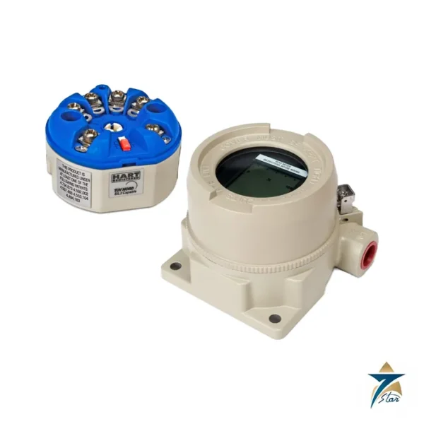
Typical companions are a field housing from the TA30 range if the transmitter must be separated from the process, the attachable TID10 display, and a DIN rail adapter clip for cabinet installation. The field housings TA30A, TA30D and TA30H are rated IP 66/67 when the transmitter is installed, and the TA30H is the flameproof version. If a display is wanted in a field housing, a housing with a glass window in the cover is required.
Configuration is done over the bus with the tools of the control system vendor, and the device carries FOUNDATION Fieldbus certification with ITK revision 6.0.1.
Selection and ordering checklist for TMT85
- Confirm the protocol: the TMT85 is FOUNDATION Fieldbus H1 only. A HART or PROFIBUS PA segment needs a different model.
- Count the sensors: two inputs are only useful if the design uses backup, drift or averaging.
- Define the sensor type and wiring (2-, 3- or 4-wire RTD, thermocouple type) for each input. Allowed combinations are limited, for example a 4-wire RTD cannot be combined with a second RTD input.
- State terminal type: screw or push-in terminals.
- State the hazardous-area approval needed and the zone and gas group of the installation.
- Decide the mounting: terminal head form B, TA30 field housing, or DIN rail clip.
- Check the segment design: supply of 9 to 32 V DC, or 9 to 17.5 V for FISCO/FNICO, and current budget of 11 mA per device.
- Note whether a TID10 display is wanted and if the head needs a window.
Installing and commissioning the TMT85
Mount the transmitter on the insert in a terminal head with enough free space, because form B heads vary in depth. Wire the sensors first, then the bus. Screw terminals accept up to 2.5 mm² and push-in terminals 0.2 to 1.5 mm²; ferrules are required with push-in terminals when flexible conductors of 0.3 mm² or smaller are used. Maximum sensor wire resistance is 50 Ω per wire for 3- and 4-wire RTDs, and a 2-wire RTD can be compensated up to 30 Ω.
After power-up, allow for the 8 s start-up, give the device a unique tag and node address on the segment, and check that the Resource block and the sensor transducer blocks report good status before linking the AI blocks into the control strategy. Verify each channel with a simulated sensor or a dry-block calibrator, and confirm that a deliberately opened sensor wire raises a diagnostic message in the host.
For maintenance, keep the order code, serial number and device ID recorded with the loop sheet. Keep the block configuration of the old unit from the control system so a replacement TMT85 can be set up the same way; the DIP switches on the optional display provide hardware settings such as write protection and simulation.
TMT85 applications in Oman and the GCC
Fieldbus temperature segments are common on newer process units in oil and gas facilities, power and water plants and petrochemical complexes around the Gulf. The TMT85 suits reactor and column temperature profiles, furnace and boiler tube skin points, compressor bearing and lube-oil temperatures, and heat-exchanger inlet and outlet monitoring, wherever a redundant pair of sensors is desired on one device.
Heat and humidity matter in the region. The transmitter is rated to 85 °C ambient and 95 % humidity with condensation permitted, but a head that sits in direct sun on an uninsulated line can exceed the ambient rating, so use a field housing and a sunshield where the head temperature is uncertain. Dust and salt-laden coastal air favour sealed housings with proper cable glands over open heads.
TMT85 within the iTEMP head transmitter family
| Model |
Protocol / output |
Inputs |
Typical use |
| TMT85 |
FOUNDATION Fieldbus H1 |
2 |
Fieldbus segments, redundancy and drift detection |
| TMT31 |
4–20 mA, PC-programmable |
1 |
Simple loops, head or DIN rail |
| TMT182B |
4–20 mA with HART 7 |
1 |
Hazardous-area head transmitter on HART loops |
| TMT142B |
4–20 mA with HART 7, Bluetooth, display |
1 |
Field housing with local indication |
What to send with your TMT85 RFQ
- Full order code and serial number from the nameplate, or a photo of the label.
- Quantity and required delivery location.
- Sensor type, wiring and measuring range on each input.
- Hazardous-area classification and the approval required.
- Terminal type, mounting method and whether a display or field housing is needed.
- Fieldbus host system and segment design (standard or FISCO).
- Any required calibration certificate or sensor matching data.
With these details we can confirm the correct variant and avoid ordering a unit that does not match the segment or the head.
Documents and quotation
A datasheet (Technical Information) for the TMT85 is attached on this page. It lists input ranges, accuracy, environment limits, dimensions and housing options, so you can check the model against your specification before ordering.
To receive a quotation, send the order code or the full requirement from the list above and Seven Star LLC will reply with availability and lead time. We supply in Oman and the GCC as an independent supplier in Muscat.
Other Models in the Itemp Transmitter Range
Seven Star LLC supplies models from the Itemp Transmitter range in Oman and the GCC. Compare the related models below and request a quote for the one that matches your application.
























Reviews
There are no reviews yet.