Brand:

Moog IN122-829A001 P-I Servo Amplifier, DIN Rail, 24 VDC

Description

Moog IN122-829A001 P-I servo amplifier overview

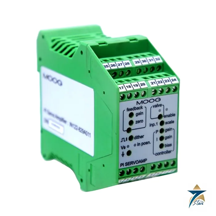
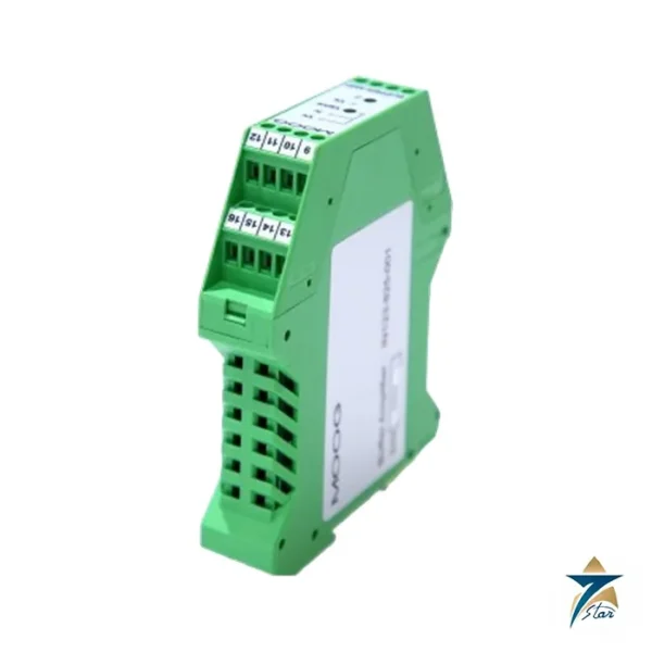
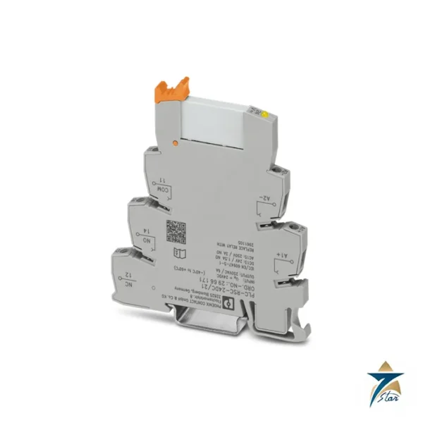
The Moog IN122-829A001 is an analog proportional and integral servo amplifier built into a compact DIN rail housing. It is intended for closed-loop hydraulic applications in which a valve must be driven from a command signal and a feedback signal. This variant of the family provides an in-position signal, and the maker lists it as equivalent to the older model G122-829A001.

Internally the IN122-829A001 sums its inputs to form an error signal, amplifies that signal proportionally and also integrates it. The proportional and integral signals are switched together and delivered as a current or a voltage to the servo valve. Many aspects of the behaviour are chosen with internal switches, so a single IN122-829A001 can serve many different applications, from a simple position loop to a pressure loop.

Setup is helped by front-panel trim pots, LED indicators and test points. The datasheet describes a step push button for tuning and an optional derivative feedback term. These features make the IN122-829A001 popular for commissioning engineers who prefer a hardware amplifier with visible signals to a software-only solution.

Key features of the Moog IN122-829A001

  • Proportional, integral or combined P and I control, chosen with an internal selector.
  • User-friendly front panel with LED indicators and test points for fast set-up and fault finding.
  • Input options: two differential inputs and one single-ended input, summed into one error signal.
  • Selectable valve drive signals: current, voltage or 4 to 20 mA output.
  • Dither that can be switched on or off, and an enable input.
  • In-position output that signals when the valve drive is within plus or minus 10 percent, depending on the variant.
  • Compact DIN rail housing, CE marked, RoHS compliant.

IN122-829A001 technical specifications

Part number IN122-829A001
Equivalent old model G122-829A001
Variant P-I amplifier with an in-position signal
Function Proportional, integral, or proportional plus integral control, switch selectable
Inputs Three: input 1 single ended, input 2 and feedback input differential (4 to 20 mA or plus or minus 10 V by switch)
Output Switch selectable voltage, current or 4 to 20 mA, single ended; selectable valve drive currents of 5, 10, 20, 30 and 50 mA
Proportional gain range 1 to 20 with the default plug-in resistor (up to 2000 with a 10 megohm resistor)
Integrator gain 1 to 45 per second
Dither 200 Hz fixed frequency, plus or minus 10 percent of valve drive, switch selectable
Enable Relay input, 24 V at 8 mA, 17 to 32 V
Supply 24 V nominal, 22 to 28 V, 200 mA maximum
Recommended fuse M205, 250 mA T (slow blow)
Terminal wire size 0.2 to 2.5 square mm (24 to 12 AWG)
Mounting DIN rail, IP 20
Ambient temperature 0 to 40 degC
Dimensions 100 mm W x 108 mm H x 45 mm D
Weight 180 g
EMC IEC 61000-6-4 emission, IEC 61000-6-2 immunity; CE marked; RoHS compliant

These data for the IN122-829A001 are taken from the maker’s datasheet. Some resistors, such as the proportional gain and input 2 resistors, are plug-in parts; the datasheet lists their default values and they must be changed only as instructed.

Typical applications in oil and gas, utilities, water and manufacturing

An analog amplifier like the IN122-829A001 is used wherever a servo valve loop is closed in hardware: position control of hydraulic cylinders on presses, rolling and forming lines, hydraulic actuators on turbine control skids in oil, gas and power plants, and hydraulic gate or damper drives in utilities and water works. In Oman and the GCC many such systems date from earlier decades and still run reliably on analog electronics.

Because the IN122-829A001 is the current-generation number of an older module, plant engineers searching for G122-829A parts can use the datasheet equivalence to find it. It is common to keep one on the shelf as a spare for each hydraulic skid.

Selection and compatibility notes for IN122-829A001

Pick the variant that matches the supervision you need: the IN122-829A001 offers an in-position signal. The other member of the family, IN122-829A011, differs in that respect. Check the input types in your loop: command, feedback and any second input may be 4 to 20 mA or plus or minus 10 V, selected by switches.

Match the output to the valve. The IN122-829A001 offers voltage, current or 4 to 20 mA output with selectable current levels of 5, 10, 20, 30 and 50 mA, and the valve supply terminal can deliver up to 300 mA. Confirm that the supply of 22 to 28 V DC is available and that the cabinet stays within 0 to 40 degC.

Installation and commissioning of the IN122-829A001

Mount the IN122-829A001 on a DIN rail, protect the 24 V supply with a 250 mA slow-blow fuse and connect wires of 0.2 to 2.5 square mm to the screw terminals. Connect the cable screens as shown in the wiring diagram and keep signal cables away from power cables.

Set the internal switches for input type, control mode, integrator limit and output type before power-up. Use the front-panel trim pots to scale input 1, set the P and I gains, adjust bias and, if needed, the dither level. The step push button helps to check the response of the loop. Document the final switch and potentiometer positions for later spare replacement.

Maintenance and care

The IN122-829A001 is an electronic module without wearing parts. Keep terminals tight, the cabinet dry and the supply within limits. When swapping a unit, copy the switch positions, plug-in resistor values and trimmer settings to the new amplifier and check the zero and gain against the old readings.

If the hydraulic axis drifts, check valve null, feedback sensor and amplifier bias separately; a valve checker is a good tool for separating hydraulic and electrical problems. Store spare amplifiers in their packaging between 0 and 40 degC.

Related products and ordering notes for IN122-829A001

Related Moog items include the IN123-825-001 buffer amplifier, the G040-119A and G040-123C valve checkers and the 761, 631 and 72 Series servo valves. The sister variant of the IN122-829A001 is IN122-829A011.

When you ask for the IN122-829A001, give the quantity, delivery location and the old model number if you are replacing a unit. Seven Star LLC is an independent supplier serving Oman and the GCC and is not affiliated with the manufacturer; the Moog name and the part number are used only to identify the product being quoted.

Frequently asked questions in short

The IN122-829A001 is a 24 VDC analog P-I servo amplifier on a DIN rail with an in-position signal. It has three inputs, selectable outputs and front-panel adjustments. The old number G122-829A001 is listed as equivalent.

Documents and quotation

The manufacturer’s datasheet for the IN122-829A001 is attached as a PDF. Send your RFQ with the part number IN122-829A001 and the quantity, and Seven Star LLC will answer with availability and lead time for Oman and the GCC.

Datasheets & Documents
  • PDF Datasheet Moog IN122-829A001 P-I Servo Amplifier Datasheet Download
Reviews (0)

Reviews

There are no reviews yet.

How would you rate this product?

It takes about 10 seconds — just tap a star. Your email is never published.

About brand

Moog is an American maker of precision motion control products, founded in July 1951 in East Aurora, New York, by Bill Moog, his brother Art Moog and Lou Geyer. Its first product was Bill Moog's electrohydraulic servo valve, which turns small electrical signals into fast, accurate hydraulic movement. Moog is still headquartered in East Aurora and is listed on the New York Stock Exchange.

Seven Star LLC lists Moog servo valves, proportional valves and an explosion-proof brushless servo motor, and sources them by model and type number for plants in Oman.

MOOG company profile

Founded July 1951, East Aurora, New York, as Moog Valve Company
Founders Bill Moog, Art Moog and Lou Geyer
Headquarters East Aurora, New York, USA
Ownership Public company, New York Stock Exchange
Product families Electrohydraulic servo and proportional valves, servo motors and drives, electromechanical actuators, test and simulation systems

Milestones

  • 1951: The Moog Valve Company starts in a corner of an airport hangar in East Aurora.
  • 1953: The US patent for Bill Moog's electrohydraulic servo valve is issued.
  • 1959: The company goes public as Moog Servocontrols Inc.

Moog servo valves and motors listed

The Moog products on this page are:

  • G761 series: two-stage flow control servo valve with mechanical feedback
  • 79 series, including D791 and D792: pilot-operated servo valves for high flow rates
  • Servo valves and servo-proportional valves for hydraulic control in general
  • G-3LM6-048-00-00-01: an explosion-proof brushless servo motor, listed here under the G400K series

Within one series, valves differ in rated flow, spool lap, coil rating, seal material and pilot arrangement. Two G761 valves with different type numbers are therefore not interchangeable without checking.

Where Moog servo valves are used

Moog servo valves control steam and gas turbine fuel and steam actuators, compressor anti-surge and guide vane actuators, steel mill gauge control, injection molding and presses, and materials test machines. In GCC power stations and gas plants the usual request is a like-for-like valve for a turbine control actuator specified by the turbine builder.

MOOG products we list

Family Examples
Hydraulic Valves & Components 72 Series Two-Stage Flow Control Servo V…, 79 Series Flow Control Servo Valve, D634 Direct Drive Servo Valve, D638 Digital p/Q Control Servo Valve, D661 Pilot-Operated Servo Valve, D671 to D675 Pilot-Operated Servo-Propor…, D791 Pilot-Operated Servo Valve, D792 High-Flow Servo Valve and 5 more
Electric Motors G-3LM6-048-00-00-01 Brushless Servo Motor

Ordering Moog parts: what we need

The nameplate on a Moog servo valve shows the model, a type designation and a serial number. Please send all three, or a clear photo. The type designation fixes rated flow, maximum operating pressure, signal and coil data, seals and connector, and is the only safe basis for quoting. If the valve was supplied through a machine builder, also give the builder's own part number. State the hydraulic fluid, especially if it is a fire-resistant phosphate ester, since that decides the seal material. For Moog servo motors, send the full model string, as in the G400K example above, and the drive it runs with.

Frequently requested MOOG models: Moog Servo Valves and Proportional Valves.

Facts checked against published Moog company histories, October 2026.

FAQ

Questions about the Moog IN122-829A001 P-I Servo Amplifier, DIN Rail,

Answers from our engineering team on installation, compatibility and integration.

01What is the difference between IN122-829A001 and IN122-829A011?
The maker lists IN122-829A001 as a P-I amplifier with an in-position signal and IN122-829A011 as a P-I amplifier with cable break detection.
02What is the old model number of the IN122-829A001?
The datasheet lists G122-829A001 as the old model equivalent to the IN122-829A001.
03What supply does the IN122-829A001 need?
A 24 V nominal supply within 22 to 28 V, with up to 200 mA, protected by a 250 mA slow-blow fuse as recommended.
04Can the IN122-829A001 run proportional only?
Yes. Internal selector switches let the amplifier work as proportional, integral or both.
05How do I request a quotation for the IN122-829A001?
Send an RFQ with IN122-829A001, the quantity and the delivery location. Seven Star LLC replies with availability and lead time.