
Related products


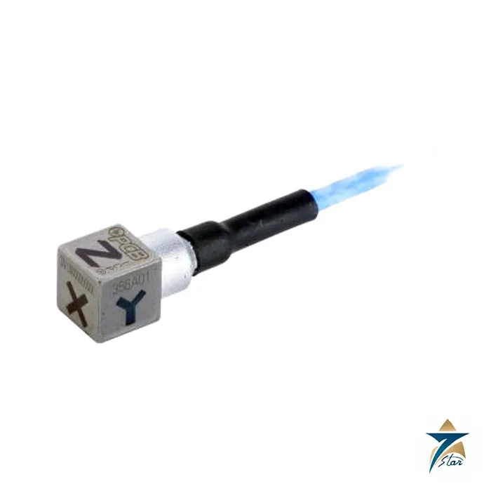
The PCB Piezotronics 356A01 is a tri-axial ICP accelerometer used for structural and modal vibration testing. The sensor measures acceleration along three orthogonal axes in a single compact housing, using ICP technology in which the signal conditioning electronics are built into the sensor and powered over the same cable as the signal. The 356A01 is a recognized model in the PCB accelerometer range for vibration measurement applications where three-axis data is required.
Tri-axial accelerometers reduce the number of mounting points and the mass added to the test structure compared with three single-axis sensors, which is important in modal testing. The 356A01 is a recognized model in the PCB structural test range. Seven Star LLC supplies the sensor with its calibration documentation and the mounting accessories for the test application. The sensor is built for repeated handling in test and measurement applications, with a rugged housing and a secure connector retention. The calibration certificate supplied with the sensor supports traceability in the test records.
ICP accelerometers integrate a small amplifier inside the sensor housing, powered by a constant current source from the conditioner over the signal cable. The sensor output is a low-impedance voltage proportional to acceleration, which can be routed over long cables without signal degradation. The 356A01 combines three of these sensing elements in one housing, aligned orthogonally, so the user records the vibration vector in three directions from a single mounting point.
Mounting the 356A01 with a stud or adhesive base on the test structure gives the stiffness needed for accurate high-frequency response. The three output channels are connected to the signal conditioner or data acquisition system, and the measured data is analysed to give the vibration levels in each axis. For modal testing, the accelerometer is moved across the structure grid while the response is recorded, building the frequency response map of the structure.
Mounting the 356A01 with a stud or adhesive base on the test structure gives the stiffness needed for accurate high-frequency response. The three output channels are connected to the signal conditioner or data acquisition system, and the measured data is analysed to give the vibration levels in each axis. For modal testing, the accelerometer is moved across the structure grid while the response is recorded, building the frequency response map of the structure. The sensor is handled with the correct tools and checked against the calibration certificate before each test series, and the mounting surface is prepared clean and flat. The signal cables are routed with the recommended strain relief, and the sensor is labelled with its serial number for the calibration records. The sensitivity and frequency response are recorded on the calibration certificate supplied with the sensor, and the certificate is used in the data analysis. The tri-axial measurement data is processed in the modal analysis software to derive the natural frequencies and mode shapes of the structure. The sensor outputs are connected to the analyser input channels with the correct ICP power settings.
The 356A01 is used for modal analysis, structural vibration testing, machinery vibration measurement and general laboratory vibration studies. It suits R&D laboratories, test departments and condition monitoring teams in the GCC region working with vibration instrumentation.
| Product | PCB Piezotronics 356A01 tri-axial accelerometer |
| Technology | ICP (integrated circuit piezoelectric) |
| Axes | three orthogonal |
| Application | structural and modal vibration testing |
| Output | low-impedance voltage proportional to acceleration |
| Mounting | stud or adhesive |
Seven Star LLC supplies PCB Piezotronics vibration sensors and accessories to test laboratories, R&D facilities and maintenance teams across Oman and the GCC. Every sensor is verified against the original PCB model number before your order is confirmed.
The PCB Piezotronics Model 356A01 is a triaxial miniature ceramic shear ICP® accelerometer housed in a 0.25-inch cube weighing just 1.0 gram, making it one of the smallest triaxial sensors in PCB’s vibration product line. It provides a sensitivity of 5mV/g ±20% across a measurement range of ±1000g peak, with a frequency response of 2–8000Hz (±5%) on the Y and Z axes and 2–5000Hz (±5%) on the X axis, and a resonant frequency of 50kHz or higher.
The sensor is rated for -54°C to +121°C (-65°F to +250°F) operation, housed in a hermetically sealed titanium case, and is adhesive-mounted rather than stud-mounted given its minimal size and weight. It requires 18–30V DC excitation with an output bias of 7–12V DC and output impedance of 200Ω or less, and connects via a 5ft (1.5m) integral 4-conductor shielded cable. An IEEE 1451.4 TEDS-compatible option is available for automated sensor identification.
This sensor is used where compact, lightweight triaxial vibration measurement is needed and mass-loading of the test article matters — modal testing, small structures and components, aerospace and automotive testing, and machinery diagnostics that need simultaneous 3-axis vibration data from a single mounting point rather than three separate single-axis sensors, which would add weight and complexity to a small test article.
Seven Star LLC supplies genuine PCB Piezotronics accelerometers, including the Model 356A01 triaxial sensor, to test laboratories, aerospace and automotive testing facilities, and industrial diagnostics teams across Oman and the wider GCC, and confirms calibration traceability (NIST via an A2LA-accredited ISO/IEC 17025 lab) and cable configuration before confirming an order.
Submit a formal inquiry through our RFQ page with the accelerometer model 356A01, the number of channels required and your signal conditioner or DAQ model. We will confirm the complete setup and respond with a formal quotation. | Inquiry Form
Choose the option that best fits your needs to get the fastest response from our team.
Automatically fill the RFQ form with this product's details for a faster process.
Manually enter multiple part numbers, specific brands, or custom requirements.



Reviews
There are no reviews yet.