Two 4-20 mA signals from one ICP accelerometer
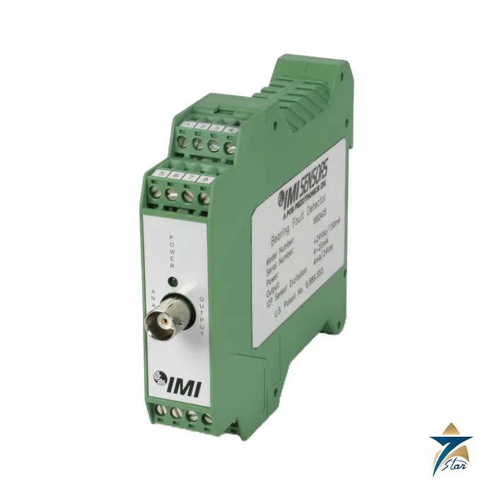
The PCB Piezotronics 682C05 is a 4-20 mA DIN rail signal conditioner that interfaces with an ICP accelerometer for bearing fault detection. It detects high-frequency impacts linked to bearing faults and lubricant starvation and gives a 4-20 mA signal proportional to their magnitude. From the same sensor it also converts overall vibration into a second 4-20 mA signal for traditional diagnostics such as unbalance and misalignment.
Because it powers the accelerometer itself with 18 VDC at 4 mA, external transmitters, signal conditioners and ICP power supplies are not needed. The module is 22.5 mm wide on a 35 mm DIN rail, with removable screw terminals and a BNC jack carrying the raw vibration signal for further frequency analysis.
Technical specifications
| Parameter |
Specification |
| Input signal |
100 mV/g (10.2 mV per m/s2) from an ICP accelerometer |
| Frequency response, overall vibration (+/-3 dB) |
10 to 1 kHz |
| Frequency response, fault (+/-3 dB) |
1 kHz or 5 kHz to 100 kHz, internal DIP switch selectable |
| Fault detector measurement range |
50 g |
| Vibration measurement range |
5 / 10 / 20 g (49 / 98.1 / 196.1 m/s2) in acceleration mode |
| Velocity range |
0.5 / 1 / 2 in/sec (12.7 / 25.4 / 50.8 mm/s) in velocity mode |
| Output range |
4 to 20 mA, two outputs (fault and overall vibration) |
| Sampling time (+/-15 %) |
7 s |
| Span (+/-5 %) |
16 mA |
| Warm-up |
Under 2 minutes |
| Supply voltage / current |
20 to 28 VDC / 150 mA or less |
| Sensor excitation |
24 VDC specified on sheet; manual lists 18 VDC at 4 mA |
| Raw vibration output |
+/-0.01 % of input; BNC jack |
| Load resistance |
500 ohm |
| Operating / storage temperature |
32 to 158 F (0 to 70 C) / -40 to 257 F (-40 to 125 C) |
| Size (width x height x depth) |
0.9 x 3.9 x 4.5 in (22.5 x 99 x 114.5 mm) |
| Weight |
Under 5 oz (142 g) |
| Housing |
Polyamide |
| Terminals |
Removable screw terminals, 24 to 14 AWG (0.2 to 2.5 mm2) |
| Mounting |
35 mm DIN rail |
Configuration and installation
Internal switches set the fault high-pass filter to 1 kHz or 5 kHz, choose acceleration or velocity mode for the overall output, select ranges of 5, 10 or 20 g (0.5, 1 or 2 in/sec) and choose peak or RMS detection for the overall vibration output. The circuit board is reached by removing the terminal connectors and releasing the tabs at the top and bottom of the enclosure.
PCB advises mounting the module in a NEMA 4 type enclosure such as the 682A00 to protect it from contamination, and not installing it where cleaning fluids or machine oils can reach it. Terminal torque must not exceed 0.5 Nm. The accelerometer cable shield lands on pin 7, and pin 3 should be tied to DIN rail or earth ground with an external wire. When the 682A01 power supply is used, mount the 682C05 to its left with a recommended separation of 4 in.
What to confirm before ordering
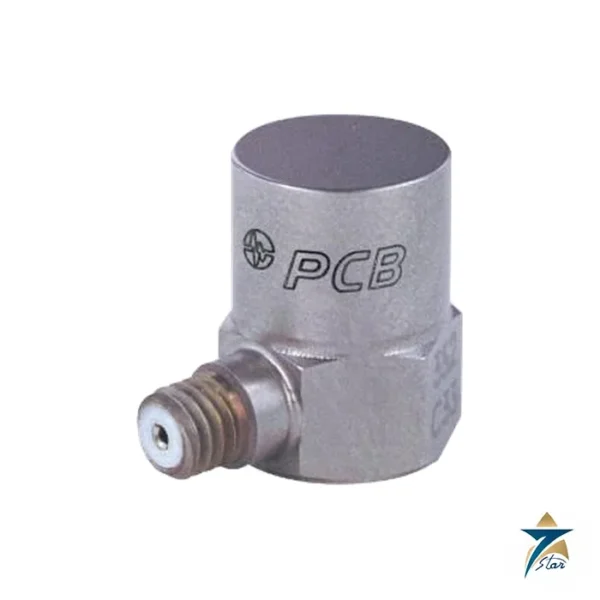
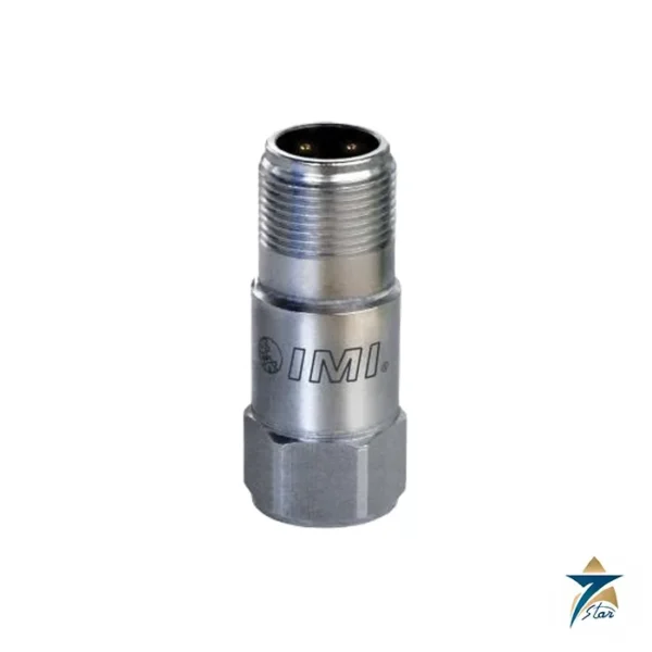
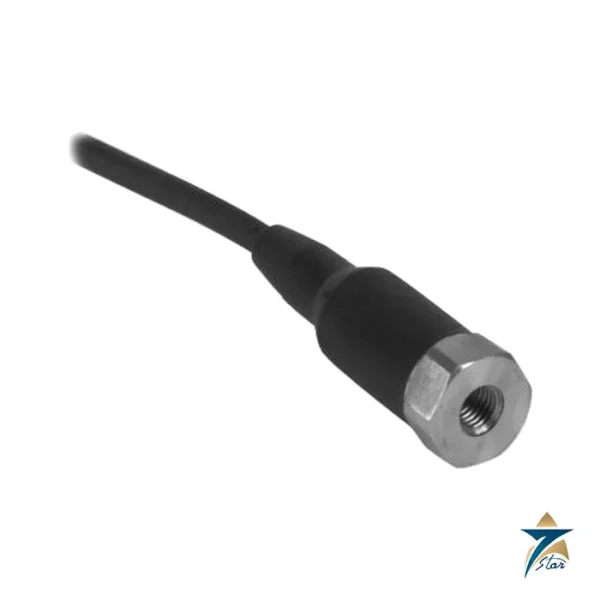
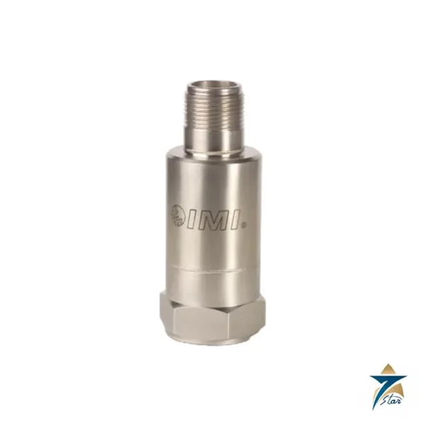
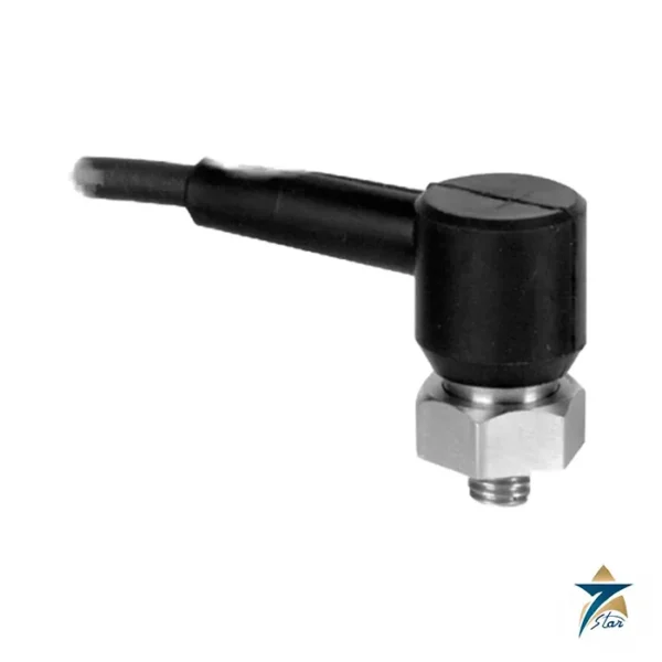
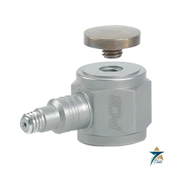
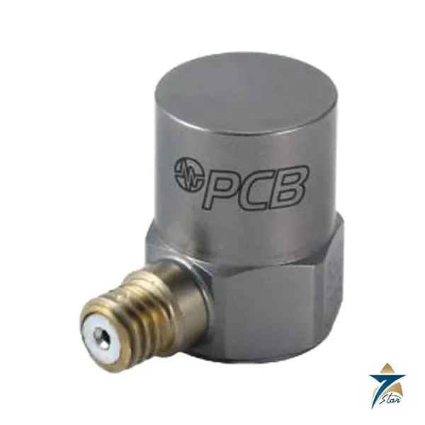
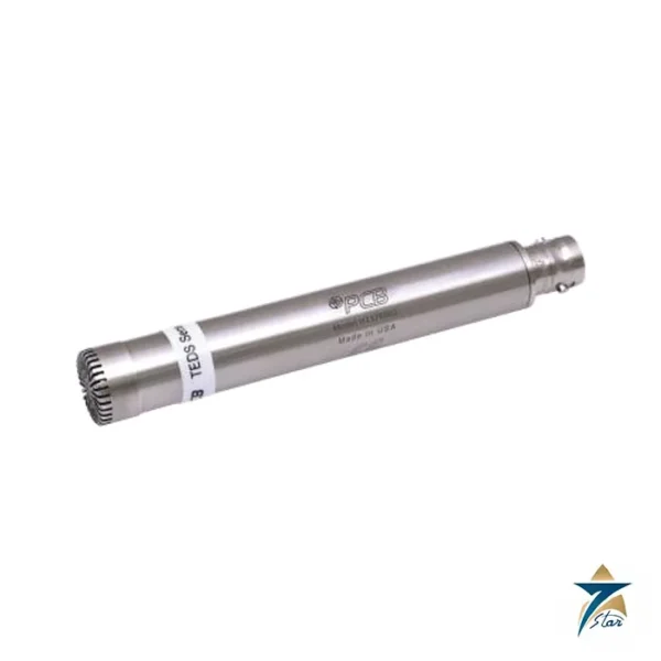
Check that your accelerometer is an ICP type of 100 mV/g, and tell us the ranges, filter and PLC or DCS input wanted. The spec sheet and manual differ slightly on the sensor excitation figure, so we confirm it with PCB for critical loops. A matching sensor is the PCB Piezotronics 603C01.
How the PCB Piezotronics 682C05 works
The module powers an ICP accelerometer and reads its signal. One path passes the signal through a high-pass filter at 1 kHz or 5 kHz, so only the high-frequency impacts of a bearing fault remain. The module measures the size of these impacts and sets a 4-20 mA output to match. A second path measures the overall vibration at lower frequencies and gives a second 4-20 mA output. The BNC jack gives the raw signal for a portable analyzer.
Where the 682C05 is used
- Motors, pumps and fans with rolling bearings
- Gearboxes and compressors
- Continuous monitoring on a PLC or DCS
- Early warning of lubricant starvation
- Plants that need low-cost condition monitoring
Selection checklist for the 682C05
- A 100 mV/g ICP accelerometer to suit the machine
- Fault filter at 1 kHz or 5 kHz
- Overall output in acceleration or velocity mode
- Range of 5, 10 or 20 g, or 0.5, 1 or 2 in/sec
- Peak or RMS detection
- Supply of 20 to 28 VDC
- Input card load of 500 ohm or less
- DIN rail space of 22.5 mm
Installation, commissioning and maintenance notes
Mount the accelerometer on a clean, flat spot close to the bearing, and fix the cable so that it does not move. Clip the module on the 35 mm DIN rail and wire the supply and the two outputs. Set the internal switches before putting the module in service. Let the module warm up for 2 minutes. Record the normal levels on a healthy machine, so that alarm limits can be set from real data.
Requesting a quotation for the PCB 682C05
Please send the accelerometer type, the machine type, the ranges and the quantity. Seven Star LLC serves industrial customers in Oman and the GCC and replies with a quotation based on the information provided.
682C05 measuring ranges
The fault detector range is 50 g. The overall vibration range is 5, 10 or 20 g in acceleration mode.
682C05 timing
The sampling time is 7 seconds, and the warm-up is under 2 minutes.
682C05 housing and terminals
The polyamide housing is 22.5 x 99 x 114.5 mm and weighs under 142 g. The screw terminals take wire from 0.2 to 2.5 mm2.
682C05 temperature range
The operating range is 0 to 70 degrees C and the storage range is -40 to 125 degrees C.
Vibration monitor records for 682C05
Keep the switch settings, the baseline levels and the alarm limits with the machine file.
Choosing the right 682C05 configuration
Start with the machine and its bearings. A 1 kHz filter suits many general machines, while a 5 kHz filter helps where low-frequency machine noise would hide small bearing impacts. Use velocity mode for the overall output when the plant limits are written in mm/s, and acceleration mode when they are written in g.
682C05 signal wiring
Both 4-20 mA outputs can go to a PLC or DCS input card with a load of 500 ohm or less. Use shielded cable for the accelerometer and keep it away from motor power cables.
Documents and quotation
The PCB operating guide for the 682C05 (manual 53377 rev C) is attached; the specification sheet is rev NR. Seven Star LLC is an independent supplier in Muscat. See Vibration Monitoring for related products.










Reviews
There are no reviews yet.