A smart impact transmitter for reciprocating compressors
The PCB Piezotronics 649A01 Reciprocating Machinery Protector (RMP) is a loop-powered smart vibration transmitter with a 4-20 mA output. PCB describes the RMP as patented: it detects impacts in reciprocating machinery and outputs a Reciprocating Fault Index (RFI) that indicates the health of the compressor.
The manual explains the reason: faults such as loose bolts, cracked rod nuts or cracked connecting or piston rods are characterised by impacting. Peak levels are high but add little energy to overall vibration, so trending overall vibration can miss them, and the time from fault to failure can be minutes. The RMP contains a piezoelectric accelerometer, a high speed true peak detector and a microprocessor, and weights the impacts it counts against two thresholds.
Technical specifications
| Parameter |
Specification |
| Output |
4-20 mA, loop powered |
| Machinery speed range |
240 to 10,000 cpm (4 to 166 Hz) |
| Time window |
0.1 to 4.0 s |
| Weighting factor |
0.2 to 16 mA |
| Trending range current |
4 to 20 mA |
| Threshold level |
2 to 50 g |
| Operating temperature |
-40 to 212 F (-40 to 100 C) |
| Storage temperature |
-40 to 257 F (-40 to 125 C) |
| Excitation voltage |
15 to 30 VDC |
| Load resistance |
50 x (Vs – 15) ohm |
| Electrical isolation |
Above 10^8 ohm |
| Overload limit (shock) |
5,000 g pk |
| Sensing element |
Embedded piezoelectric accelerometer |
| Housing / sealing |
Stainless steel / welded hermetic |
| Size (hex x height) |
1.25 in x 2.60 in (32 mm x 66 mm) |
| Weight |
7 oz (198 g) |
| Mounting |
1/4-28 UNF; torque 3 to 5 ft-lb (4 to 7 Nm) |
| Connection |
Top; pin A 4-20 mA positive, pin B 4-20 mA negative |
| Supplied accessory |
Model 081A41 mounting stud, 1/4-28 socket head set screw, brass tip, 5/8 in |
Operating principle and programming
The RMP examines a time window, finds each peak and compares it with Threshold Level 1 and Threshold Level 2. If no peak exceeds either, the output is proportional to the maximum peak seen, which gives acceleration trending. If at least one peak exceeds a threshold, the RFI is calculated by counting peaks above each threshold, applying separate weighting factors, and adding the trending range current. Threshold 2 usually carries more weight because those impacts are more severe.
Every unit is factory programmed. An optional USB Programming Kit allows field changes in Dependent Mode, where all parameters follow the machine speed, or Independent Mode, where each is set by the user. Output goes to PLC, DCS, SCADA or plant information systems for 24/7 protection of critical compressors. The manual features guidance for gas compressors and piston pumps, and notes intrinsically safe EX versions (CSA, ATEX).
What to confirm before ordering
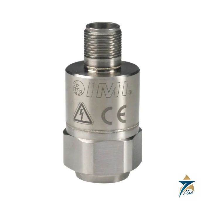
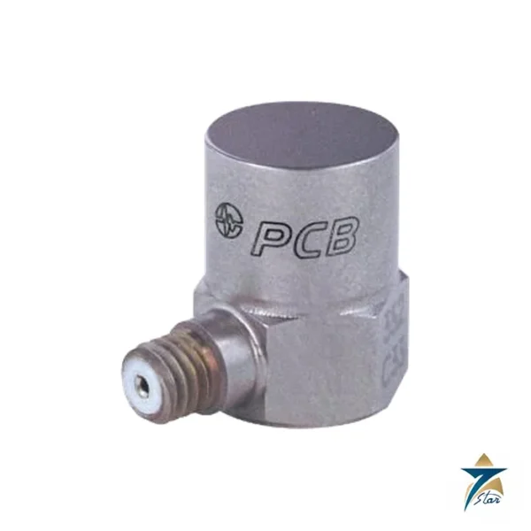
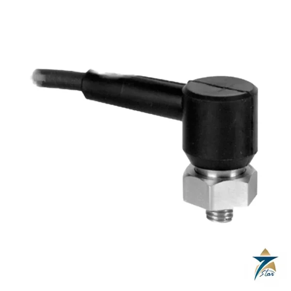
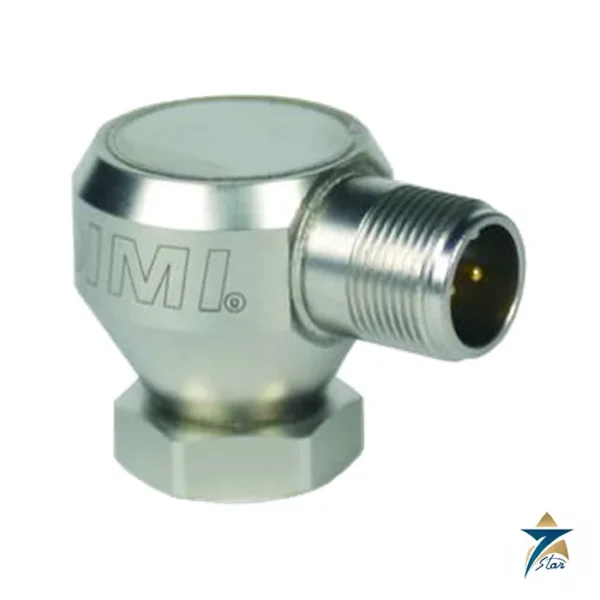
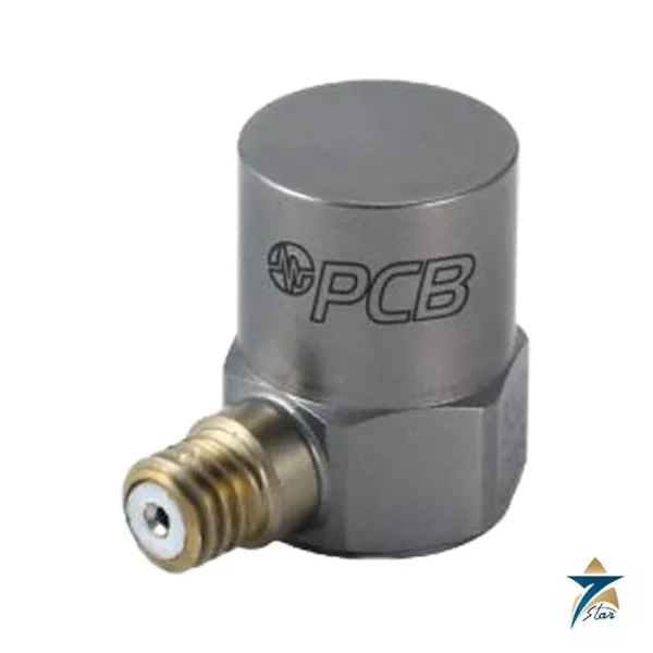
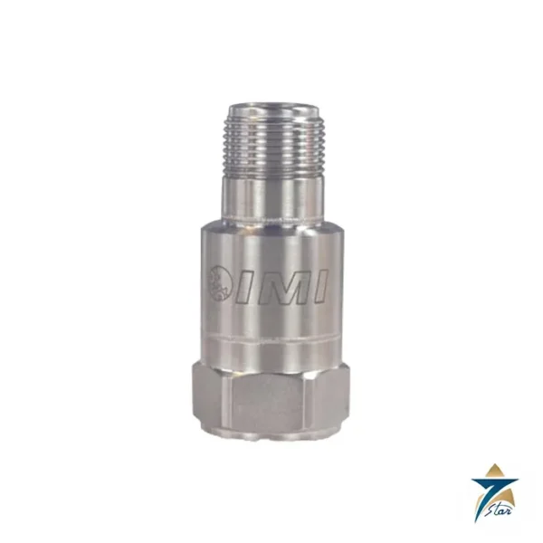
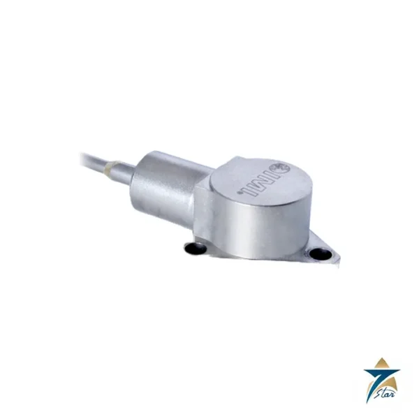
Please give the machine type, rpm, cylinder count, expected baseline vibration, the loop supply voltage and whether an EX version is needed. The photo on the manufacturer page shows a 649A03 family sensor, so check the received part number. For a simpler 4-20 mA velocity signal, see the PCB Piezotronics 640B01.
How the PCB 649A01 works
The 649A01 contains a piezoelectric accelerometer, a fast true-peak detector and a microprocessor in one welded stainless steel housing. It watches a time window between 0.1 and 4 seconds, finds each acceleration peak and compares it with two threshold levels. If no peak crosses a threshold, the 4-20 mA output follows the highest peak, so it can be used for acceleration trending. If peaks cross a threshold, the unit counts them, applies a weighting factor to each level and adds the result to the trending current. The output is the Reciprocating Fault Index, which rises as impacting becomes more severe.
Where the 649A01 is used
- Reciprocating compressors in gas and process plants.
- Crosshead and frame monitoring.
- Machinery protection loops with a trip or alarm at the controller.
- Engines and pumps with strong impact signatures.
- Remote sites where a simple loop-powered signal is preferred.
Selection checklist for the 649A01
- Machine speed within 240 to 10,000 cpm, which is 4 to 166 Hz.
- Time window of 0.1 to 4.0 s.
- Weighting factor of 0.2 to 16 mA.
- Threshold level of 2 to 50 g.
- Loop supply of 15 to 30 V DC, with a load resistance of 50 x (Vs – 15) ohms.
- Operating range of -40 to 100 degrees C.
- Shock limit of 5,000 g peak.
- Mounting thread 1/4-28 UNF and torque of 3 to 5 ft-lb.
- Size of 1.25 in hex by 2.60 in and weight of 198 g.
- Connection with pin A as the positive and pin B as the negative of the loop.
Installation, commissioning and maintenance notes
Mount the sensor on a clean, flat surface at the point where impacts reach the structure, using the supplied 081A41 stud and the stated torque. Wire the loop with the correct polarity and keep it away from heavy power cables. The thresholds and weights are set at the factory for the application, so record the settings with the unit number before installation. During commissioning, compare the output with the machine at normal load and note the baseline for future trends. If the index rises, inspect the machine according to your maintenance procedure.
Requesting a quotation for the PCB 649A01
Send the machine type, the running speed and the settings you need. Seven Star LLC serves industrial customers in Oman and the GCC and replies with a quotation based on the information provided.
Why impacts need a separate sensor
Faults such as loose bolts or cracked rod nuts create impacts with high peaks but little energy, so overall vibration may not change, while the peak-based index does.
Two thresholds
Threshold 2 normally carries more weight, because the impacts above it are more severe than those above Threshold 1.
Sealing
The housing is welded and hermetic, which suits oily and dirty compressor skids.
Sensor records
Log the serial number, the settings and the baseline output after commissioning.
Documents and quotation
The PCB operating guide for the 649AX1 series (manual 38281 rev F) is attached, and the 649A01 spec sheet is rev D. Seven Star LLC is an independent supplier in Muscat. See Vibration Monitoring.







Reviews
There are no reviews yet.