A compact quartz force sensor for compression, tension and impact
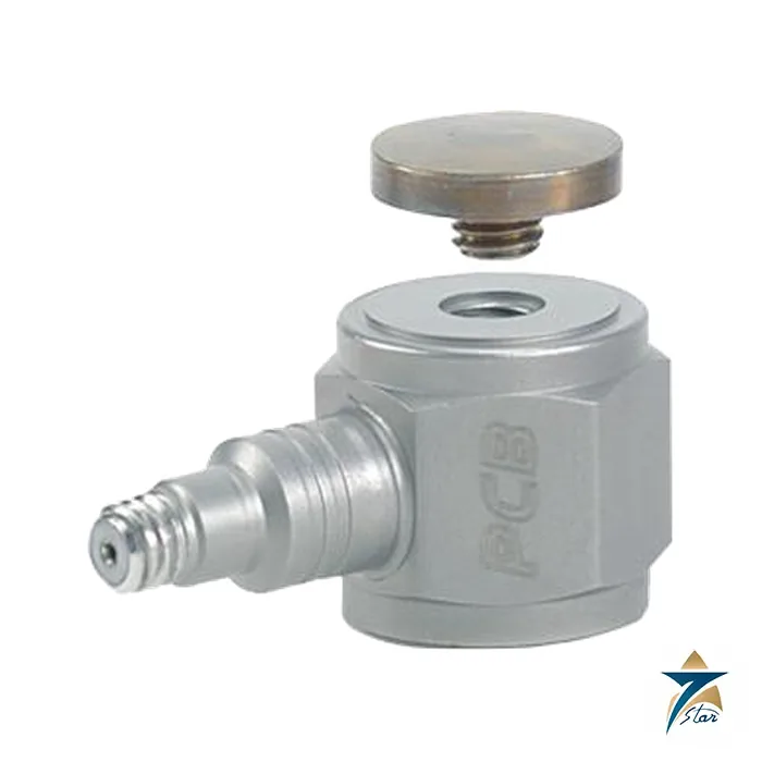
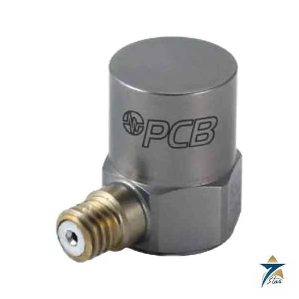
The PCB Piezotronics 208C02 is an ICP force sensor with a 100 lb (0.4448 kN) measurement range in both compression and tension and a sensitivity of 50 mV/lb. It has a stainless steel hermetic body 0.625 in across and 0.5 in of sensing surface, and a 10-32 female thread for mounting.
Force sensors of the 208C series are used for dynamic tests such as impact, tapping and structural force input. The sensor is powered by a standard constant current ICP source, and its low frequency response of 0.001 Hz (from a discharge time constant of at least 500 s) lets it follow slowly changing forces better than short time constant types.
Technical specifications
| Parameter |
Specification |
| Sensitivity (+/-15 %) |
50 mV/lb (11,241 mV/kN) |
| Measurement range, compression / tension |
100 lb / 100 lb (0.4448 kN each) |
| Maximum static force |
600 lb compression (2.669 kN); 500 lb tension (2.224 kN) |
| Broadband resolution (1 to 10,000 Hz) |
0.001 lb-rms (0.004 N-rms) |
| Low frequency response (-5 %) |
0.001 Hz |
| Upper frequency limit |
36 kHz (estimated) |
| Non-linearity |
1 % FS or less |
| Temperature range |
-65 to +250 F (-54 to +121 C) |
| Temperature coefficient of sensitivity |
0.05 %/F or less |
| Discharge time constant |
500 s or more |
| Excitation voltage / constant current |
20 to 30 VDC / 2 to 20 mA |
| Output impedance / bias voltage |
100 ohm or less / 8 to 14 VDC |
| Output polarity (compression) |
Positive |
| Stiffness |
6 lb/uin (1.05 kN/um) |
| Size (hex x height x sensing surface) |
0.625 x 0.625 x 0.500 in (15.88 x 15.88 x 12.7 mm) |
| Weight |
0.80 oz (22.7 g) |
| Housing / sealing |
Stainless steel / hermetic |
| Connector / position |
10-32 coaxial jack / side |
| Mounting thread |
10-32 female |
| Supplied accessories |
080A81 thread locker, 081B05 mounting studs (2), 084A03 impact cap, M081A62 metric studs (2) |
Options and installation
Options are N (negative output polarity in compression), TLD (TEDS capable per IEEE 1451.4) and W (water resistant cable). For higher ranges PCB suggests dedicated ring, link or impact sensor configurations, since the 208C family covers compression to 5,000 lb and tension to 500 lb across its models.
Mount the sensor between flat, parallel, clean surfaces with the supplied stud and thread locker, and use the impact cap when the sensor is struck directly. Choose the range with margin above the expected peak force.
The stiffness of 6 lb/uin (1.05 kN/um) and the 36 kHz upper frequency limit, which PCB estimates from rigid body dynamics calculations, show how stiff and fast the sensor is in the load path. Maximum static force is 600 lb in compression and 500 lb in tension, well above the 100 lb dynamic range, which leaves static headroom. Output polarity in compression is positive as standard, with the N option for negative.
What to confirm before ordering
This force sensor is a dynamic ICP type and is not suited to long static load weighing, so confirm the application. Send the force level, tension or compression, the signal conditioner, and any TEDS or water-resistant need.
The manual given with the request is a general 208 series guide, so we host the model data sheet instead.
Choosing the 208C02 for a test
The 208C02 suits dynamic measurements where the forces of interest fall within its measurement range and change quickly, such as impacts, short pulses, tapping and repetitive loading. Its high stiffness means the sensor adds very little compliance to the load path, so it does not noticeably change the behaviour of the structure being tested. If the expected peak force is well above the range of this model, another member of the 208C family or a different sensor configuration should be chosen, as noted above.
Consider also how the force will be applied. Compression and tension are both covered, but each load direction has its own static limit in the table, and the mounting must be designed for the direction actually used.
Typical applications
Typical uses include structural testing where a measured force input is needed, impact testing with the supplied impact cap, monitoring of press-fit and crimping forces, drop and tapping tests, and laboratory studies of dynamic loading on components. Because the sensor is small and light, it can be installed in compact test fixtures where larger load cells would not fit.
Signal conditioning and cabling
As an ICP sensor, the 208C02 needs a constant current excitation source within the voltage and current limits listed in the table. Many data acquisition systems and signal conditioners provide this directly. Use a low-noise coaxial cable with the correct connector for the side jack, secure it so it does not pull on the sensor during the test, and route it away from power cables. Check the bias voltage before starting a measurement; a value outside the listed range suggests a cabling or excitation problem.
When the sensor is used with the TLD option, the TEDS data allows a compatible acquisition system to read the sensor identification and sensitivity automatically, which reduces setup errors in test rooms with many channels.
Mounting and handling good practice
Prepare the mounting surfaces carefully so they are flat, parallel and clean, because uneven contact can distort the reading and load the sensor unevenly. Use the supplied studs and thread locker as described in the PCB documentation, and avoid over-tightening. Handle the sensor with care, keep the connector clean and covered when not in use, and avoid dropping it, since a shock outside the intended test can affect the measurement. Before each test series, run a short check with a known input to confirm that the channel responds as expected and that the sensitivity entered in the acquisition software matches the calibration data for the sensor.
How to specify your request for quotation
Give the model number 208C02, the quantity and any option suffix needed, such as N, TLD or W. Mention the signal conditioner or acquisition system in use and the type of test, so that the choice of range and options can be checked before ordering.
Documents and quotation
The PCB 208C02 specification sheet (Rev. K) from the product page is attached, because the 208C manual covers several models. Seven Star LLC is an independent supplier in Muscat. See Vibration Monitoring.








Reviews
There are no reviews yet.