
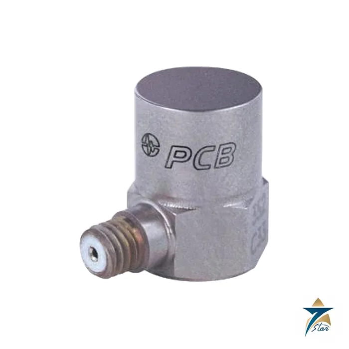
The PCB Piezotronics 352C33 is a miniature, general-purpose ICP® accelerometer from the PCB Piezotronics vibration division, and it is one of the best-known test and measurement accelerometers in use today. Weighing only 5.8 g, with 100 mV/g sensitivity, a ±50 g pk range and a frequency response of 0.5 to 10,000 Hz within ±5%, it is the sensor many engineers reach for when they need accurate vibration data from small structures, rotating machines and test rigs without mass-loading the object under test.
Seven Star LLC supplies the PCB Piezotronics 352C33 to engineering consultancies, university laboratories, OEM test departments and plant reliability teams in Oman and the GCC. From Muscat we provide engineering support, including the mounting accessories, coaxial cables and IEPE signal conditioners that a complete measurement chain requires.
The PCB Piezotronics 352C33 uses a ceramic sensing element in shear configuration. Under vibration, an internal seismic mass loads the ceramic in shear and generates a charge proportional to acceleration; built-in ICP® microelectronics convert that charge into a low-impedance voltage. In general, shear designs give low base strain sensitivity and good thermal stability, and the datasheet confirms a base strain sensitivity of 0.003 g/µε for this model, so the signal reflects real motion rather than bending of the mounting surface.
Being an IEPE device, the sensor needs a constant current supply of 2 to 20 mA from an 18 to 30 VDC source, which is provided by most data acquisition systems, dynamic signal analyzers and portable vibration meters. The output bias voltage is 7 to 12 VDC and the output impedance is at most 200 ohm, so the signal can be carried over ordinary coaxial cable with very good noise immunity.
The housing is titanium with a hermetic seal, measuring 0.44 in hex by 0.62 in high (11.2 mm x 15.7 mm). A side-exit 10-32 coaxial jack keeps the profile low and the 10-32 female mounting thread accepts the supplied studs; recommended mounting torque is 10 to 20 in-lb (113 to 226 N-cm). The low mass and stiff construction place the resonant frequency at or above 50 kHz, which keeps the upper part of the usable band flat.
The datasheet lists a range of factory options. The HT option extends the operating temperature to +163 °C with some changes to bias and frequency data, the J option adds ground isolation, the W option provides a sealed integral water-resistant cable, and the T, TLA, TLB, TLC and TLD options add TEDS digital memory to IEEE P1451.4 or IEEE 1451.4 for automatic sensor identification in compatible data acquisition systems.
The mounting method affects the result. As a general rule, stud mounting on a smooth, flat surface gives the widest usable bandwidth, adhesive bases come close for most work, and wax is convenient for quick surveys at moderate temperatures and lower frequencies. Because the PCB Piezotronics 352C33 is supplied with an adhesive base, petro wax and two studs, an engineer can choose the right method on site. The side connector also lets the cable be taped down close to the surface, which reduces cable whip, a frequent source of noise at low frequencies.
Selecting the PCB Piezotronics 352C33 rather than a heavier industrial sensor makes sense whenever the test object is light, such as instrument tubing, small brackets or thin panels, since a heavy sensor can shift the natural frequencies being measured.
The PCB Piezotronics 352C33 is valued for the following characteristics:
Typical uses of the PCB Piezotronics 352C33 include modal and structural testing of skids and pipe supports, troubleshooting of resonance on pump baseplates, acceptance testing of motors and fans, and laboratory vibration measurement in product development. In the oil, gas and power sectors in Oman, reliability engineers often use it during root-cause investigations, where a few lightweight sensors are attached temporarily with wax or adhesive to map operating deflection shapes on a problem machine before a permanent monitoring solution is designed.
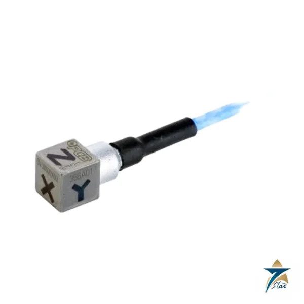
Seven Star LLC supplies the PCB Piezotronics 352C33 with cables, mounting bases and signal conditioning, and can recommend permanent industrial sensors when a temporary investigation turns into a monitoring program. On this site you can find the rugged PCB Piezotronics 356A01 tri-axial accelerometer for three-axis measurements, the PCB Piezotronics 378B02HT acoustic sensor for sound measurements, and the CEMB N600 portable vibration analyzer and dynamic balancer, which can work with IEPE accelerometers in field balancing tasks.
Data for the PCB Piezotronics 352C33 is taken from the PCB Piezotronics datasheet, revision H:
| Parameter | Specification |
|---|---|
| Model | 352C33 |
| Type | General-purpose ICP® accelerometer |
| Sensitivity (±10%) | 100 mV/g (10.2 mV/(m/s²)) |
| Measurement range | ±50 g pk |
| Frequency range (±5%) | 0.5 to 10,000 Hz |
| Frequency range (±10%) | 0.3 to 15,000 Hz |
| Resonant frequency | ≥50 kHz |
| Broadband resolution (1 to 10,000 Hz) | 0.00015 g rms |
| Non-linearity | ≤1% |
| Transverse sensitivity | ≤5% |
| Overload limit (shock) | ±5,000 g pk |
| Temperature range (operating) | -54 to +93 °C |
| Base strain sensitivity | 0.003 g/µε |
| Excitation voltage / current | 18 to 30 VDC / 2 to 20 mA |
| Output impedance | ≤200 ohm |
| Output bias voltage | 7 to 12 VDC |
| Discharge time constant | 1.0 to 2.5 s |
| Sensing element / geometry | Ceramic / shear |
| Housing / sealing | Titanium / hermetic |
| Size (hex x height) | 11.2 mm x 15.7 mm |
| Weight | 5.8 g |
| Electrical connector | 10-32 coaxial jack, side exit |
| Mounting thread / torque | 10-32 female / 113 to 226 N-cm |
| Options | HT high temperature, J ground isolated, T/TLA/TLB/TLC/TLD TEDS, W water-resistant cable |
To obtain the PCB Piezotronics 352C33 or one of its option versions, contact Seven Star LLC with the quantity, option codes and the data acquisition hardware you use. The PCB Piezotronics 352C33 datasheet can be downloaded from this page. Our Muscat instrumentation team will confirm availability and lead time, prepare a formal offer and assist with measurement setup for customers across Oman and the GCC.
Browse PCB Piezotronics products by category: Vibration.
Choose the option that best fits your needs to get the fastest response from our team.
Automatically fill the RFQ form with this product's details for a faster process.
Manually enter multiple part numbers, specific brands, or custom requirements.







Reviews
There are no reviews yet.