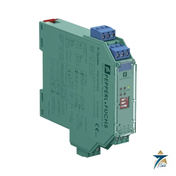
Pepperl+Fuchs KFD2-STC4-Ex1.2O overview
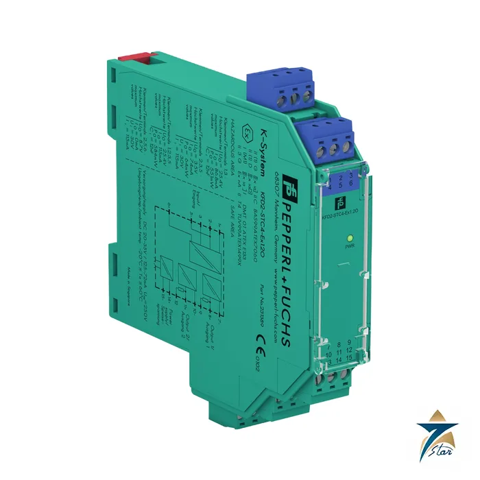
The Pepperl+Fuchs KFD2-STC4-Ex1.2O is the dual-output version of the KFD2-STC4 SMART transmitter power supply from Pepperl+Fuchs. It supplies 2-wire and 3-wire SMART transmitters in a hazardous area, can be used with 2-wire SMART current sources, and repeats the transmitter current to the safe area as two separate isolated 0/4 to 20 mA outputs on terminals 7 to 9 and 10 to 12. This lets one field transmitter feed, for example, a control system and a safety system or recorder at the same time.
The datasheet released on 5 June 2023 gives SIL 3 as the functional safety level and lists HART, BRAIN and Foxboro as supported protocols. Test sockets and an internal 250 ohm resistor for each output are provided. The datasheet adds an important note: both output loads must be connected to ensure complete and correct operation within the specification, and an open circuit on one output does not affect the other output but can cost up to 0.7 V of transmitter supply voltage.
Key features of the Pepperl+Fuchs KFD2-STC4-Ex1.2O
- One input channel with two galvanically separated 0/4 to 20 mA outputs
- Supplies 2-wire and 3-wire SMART transmitters and 2-wire SMART current sources
- Safety Integrity Level SIL 3 stated in the datasheet
- HART, BRAIN and Foxboro protocols with bi-directional digital communication
- Each output load from 0 to 550 ohm at 20 mA
- Operated from the Power Rail or terminals 14 and 15 on 20 to 35 V DC
- Marking [Ex ia Ga] IIC, [Ex ia Da] IIIC and [Ex ia Ma] I, with Zone 2 marking Ex nA for the module
- 20 mm wide housing type B2, IP20, minus 20 to 60 degrees C
KFD2-STC4-Ex1.2O technical specifications
The values below are taken from the manufacturer datasheet of the KFD2-STC4-Ex1.2O, release date 2023-06-05. Always confirm the current datasheet and the certificates before final engineering.
| Parameter |
Value |
| Model |
KFD2-STC4-Ex1.2O, SMART Transmitter Power Supply, 1-channel isolated barrier, two outputs |
| Signal type |
Analog input |
| Safety Integrity Level |
SIL 3 |
| Rated supply voltage |
20 to 35 V DC (Power Rail or terminals 14+, 15-) |
| Power dissipation / consumption |
1.8 W / 2.4 W |
| Input |
0/4 to 20 mA, terminals 1+, 2-, 3 or 5-, 6+ |
| Open circuit voltage / short-circuit current |
22.7 V / 38 mA (terminals 1+, 3-) |
| Available voltage (terminals 1+, 3) |
At least 16 V at 20 mA |
| Outputs |
0/4 to 20 mA, terminals 7-, 8+, 9 and 10-, 11+, 12; load 0 to 550 ohm at 20 mA; overload above 25 mA |
| Deviation at 20 degrees C |
Up to 10 microamperes including calibration, linearity, hysteresis, load and supply fluctuation |
| Influence of ambient temperature |
0.25 microamperes per K |
| Settling time / rise time |
200 microseconds / 20 microseconds |
| Isolation |
Output to output and output to supply: functional insulation, 50 V AC; input to others: safe isolation, peak value 375 V |
| Hazardous-area marking |
(1)G [Ex ia Ga] IIC, (1)D [Ex ia Da] IIIC, (M1) [Ex ia Ma] I |
| EU-type examination certificate |
BAS 99 ATEX 7060 X |
| Field terminals 1+, 3- |
Uo 25.4 V, Io 86.8 mA, Po 551 mW, Ci 12 nF, Li 0 mH |
| Zone 2 certificate |
TUV 99 ATEX 1499 X, marking Ex nA II T4 |
| IECEx |
IECEx BAS 04.0016X; IECEx CML 15.0055X |
| Ambient temperature |
Minus 20 to 60 degrees C |
| Dimensions / mass |
20 x 124 x 115 mm (W x H x D), housing type B2 / approx. 200 g |
| Degree of protection / mounting |
IP20, screw terminals / 35 mm DIN rail |
Remember the note in the datasheet that both output loads need to be connected for specified operation. If only one output is used, terminate the second output with a suitable load or follow the guidance in the manual.
Typical applications in oil and gas, utilities, water and manufacturing
Loop-powered SMART transmitters for pressure, differential pressure, level and temperature are everywhere in refineries, gas gathering stations and desalination plants in Oman, and every one of them that sits in a hazardous area needs an interface to the control room. The KFD2-STC4-Ex1.2O fills that role in marshalling cabinets that feed DCS and PLC analog input cards, while letting HART communication pass through for configuration and diagnostics.
In utilities, water and wastewater works, and in manufacturing sites across the GCC, the same module is used where a transmitter is installed near a fuel store, a chemical dosing area or a biogas digester. Maintenance teams value the integrated test sockets because a handheld communicator can be connected without opening the loop, which shortens routine calibration and loop-check work on the KFD2-STC4-Ex1.2O channel.
Selection and compatibility notes for KFD2-STC4-Ex1.2O
Start with the transmitter. Confirm that its supply voltage requirement, its maximum current and its entity parameters match the field-side data of the KFD2-STC4-Ex1.2O, and confirm that the control system input accepts the output type of the module. The loop must also offer enough load resistance for HART communication, which is why the datasheet describes an internal 250 ohm resistor that can be used when the loop resistance is too low.
Next consider the cabinet. Devices of this family snap onto a Power Rail or are supplied through dedicated terminals, so decide early whether power will be distributed by rail or wired point to point. If your plant standard calls for a different housing width, channel count or SIL level, tell us before ordering so that we can compare neighbouring variants of the KFD2-STC4-Ex1.2O against your loop list.
The two outputs make this model attractive for plants that keep a basic process control system and an independent safety instrumented system on the same transmitter. Check that both receiving inputs present loads within the 0 to 550 ohm range at 20 mA before you choose the KFD2-STC4-Ex1.2O.
Installation and commissioning of the KFD2-STC4-Ex1.2O
Before mounting the KFD2-STC4-Ex1.2O, confirm the field device and cable parameters against the entity values in the datasheet and the certificate, and decide whether the module will be powered from a Power Rail or from its own supply terminals. Mount it on a 35 mm DIN rail in a clean, ventilated cabinet in the safe area, keep hazardous-area and safe-area wiring physically separated and labelled, and respect the spacing and marking required by your site rules for intrinsically safe circuits. Terminate both outputs with their loads before testing, as the datasheet requires, and label the two output channels clearly so that control and safety systems are not swapped.
Wire the KFD2-STC4-Ex1.2O only to the terminal assignment printed in the wiring diagram, tighten the screws and check that no strands are left outside the clamp. After applying the supply, check the power indication, then simulate the field signal and prove the complete loop from field to control system before the plant is handed over. Record the as-found readings so that later loop checks of the KFD2-STC4-Ex1.2O can be compared with the commissioning values.
Maintenance and service life
The KFD2-STC4-Ex1.2O has no serviceable parts, so maintenance is mostly inspection. During planned shutdowns, check terminals for looseness and corrosion, verify the supply voltage at the module, and repeat the loop check that was recorded at commissioning. In coastal and humid locations such as Muscat, Sohar and Duqm, a clean, dry and sealed cabinet greatly extends the life of any electronic interface. During loop checks, verify both outputs, not just the one in use, because a missing load on one output reduces the transmitter supply voltage by up to 0.7 V.
If a loop drifts out of tolerance or the unit shows no power indication with a healthy supply, replace the module instead of attempting a repair, and keep the replacement documentation in the loop folder. Certified intrinsically safe equipment must not be modified, and any change to cabling, load or field device should be re-assessed against the KFD2-STC4-Ex1.2O entity parameters before it returns to service.
Related products and ordering notes
Customers who ask for the KFD2-STC4-Ex1.2O often need neighbouring models or accessories from the same system, such as other KFD2 and KCD2 SMART transmitter power supplies, the Power Rail and power feed modules, and the neighbouring switch amplifiers and current drivers. If you are standardising a cabinet on one family, send us the loop list and we can quote the matching modules together.
When you send an enquiry for the KFD2-STC4-Ex1.2O, quote the full part number exactly as printed on the nameplate, the quantity and the intended application. If you are replacing an installed unit, a photograph of the nameplate helps us confirm the exact variant you need. We can arrange a quotation with delivery to Oman and across the GCC.
Frequently asked questions about KFD2-STC4-Ex1.2O
The KFD2-STC4-Ex1.2O is a SIL 3 isolated barrier that powers SMART transmitters and delivers two isolated 0/4 to 20 mA outputs, each able to drive up to 550 ohm, with both loads required for specified operation.
Documents and quotation
A copy of the manufacturer datasheet for the KFD2-STC4-Ex1.2O is attached to this page for your engineering review. To request a quotation, send the RFQ with the part number KFD2-STC4-Ex1.2O, the quantity, the delivery location and any certification or documentation requirements, and we will reply with availability and lead time. Please check the specification against your loop or system requirements before ordering.
Seven Star LLC is an independent supplier serving Oman and the GCC and is not affiliated with Pepperl+Fuchs. Product names and part numbers are used only to identify the item you ask for.
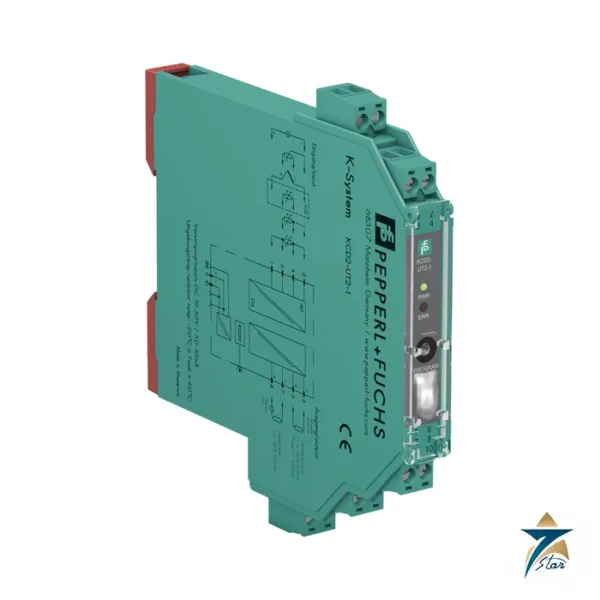
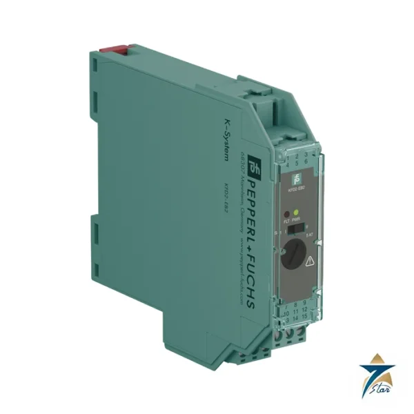
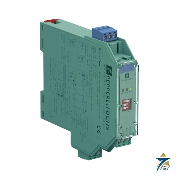
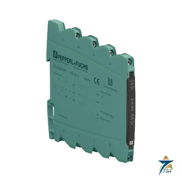
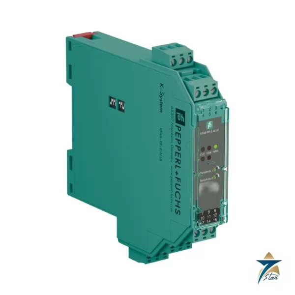
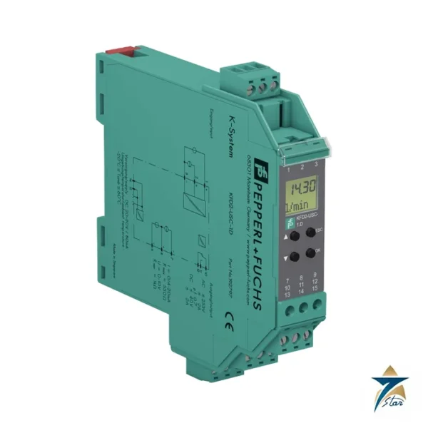
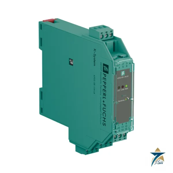
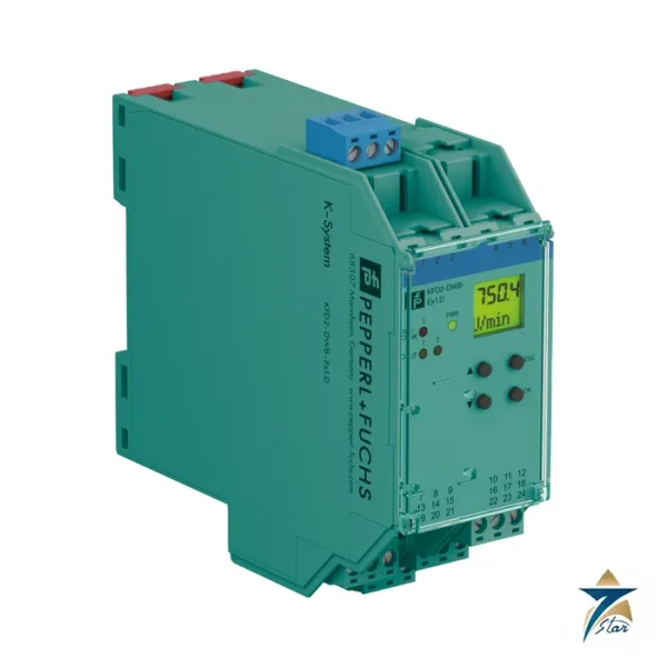
Other Models in the K System Range
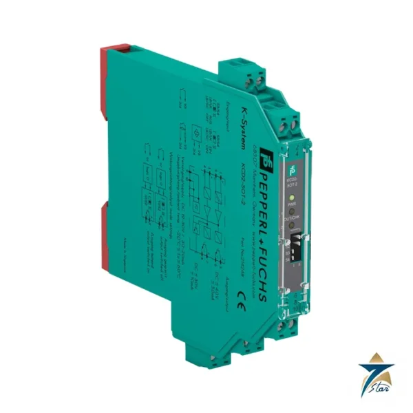
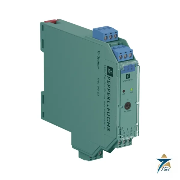
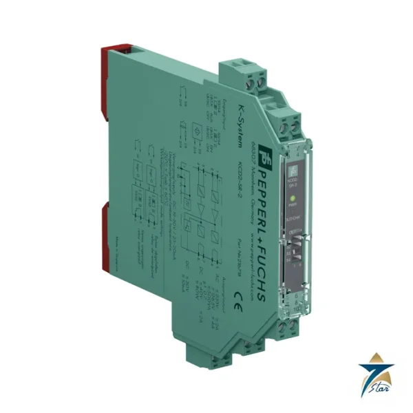
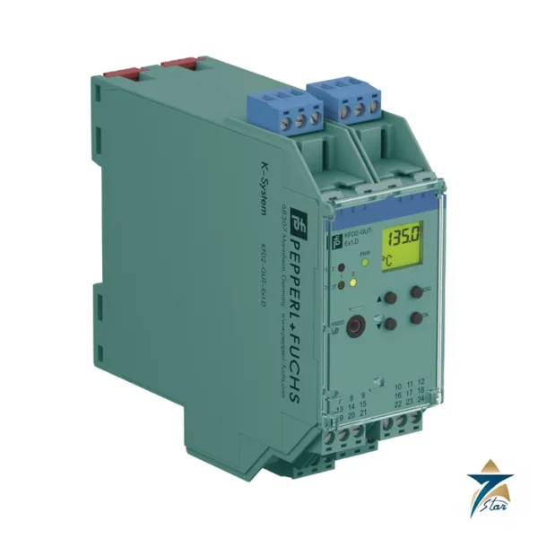
Seven Star LLC supplies models from the K System range in Oman and the GCC. Compare the related models below and request a quote for the one that matches your application.






Reviews
There are no reviews yet.