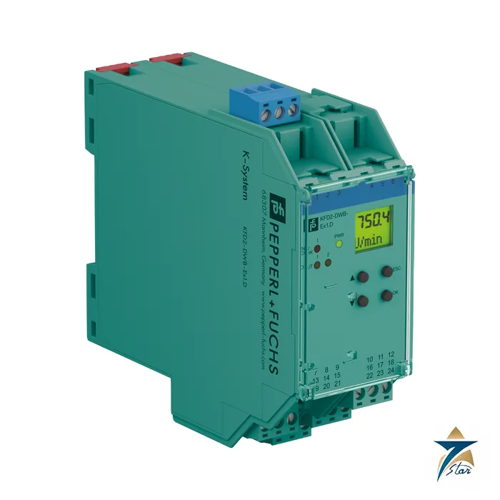
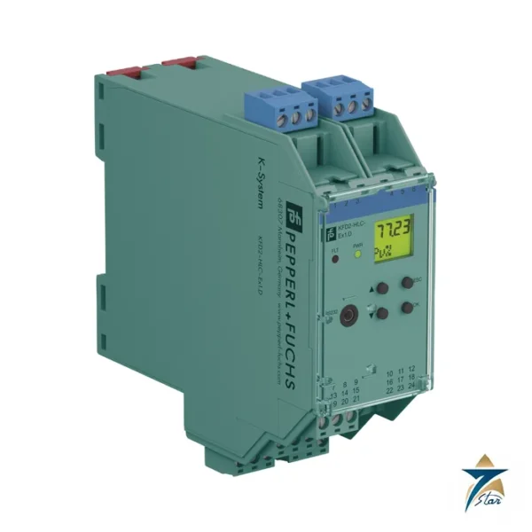
KFD2-DWB-Ex1.D rotation speed monitor with relay outputs
The KFD2-DWB-Ex1.D is an isolated barrier from Pepperl+Fuchs that does more than repeat a contact: it measures the pulse frequency of a NAMUR sensor or mechanical contact from a hazardous area and compares it with limits that the user programs. Overspeed and underspeed conditions switch two relays, which makes it a compact speed switch for fans, pumps and conveyors.
The name reads: KFD2 for the 24 V DC isolated barrier range, DWB for the rotation speed (Drehzahl) monitor, Ex1 for a single measuring channel, and .D for the version with a display and keypad programming.
Seven Star LLC supplies this module in Oman and the GCC as an independent supplier in Muscat.
Technical specifications of the KFD2-DWB-Ex1.D
| Parameter |
Specification |
| Manufacturer / part number |
Pepperl+Fuchs KFD2-DWB-Ex1.D |
| Input I (intrinsically safe) |
NAMUR or dry contact, terminals 1+, 3-; pulse duration > 50 µs; 0.001 to 5000 Hz |
| Line fault detection |
Breakage I ≤ 0.15 mA, short-circuit I > 6.5 mA |
| Input II (non-intrinsically safe) |
Start-up override, terminals 13+, 14-; active at I > 4 mA for min. 100 ms, passive at I < 1.5 mA |
| Start-up override |
1 to 1000 s, adjustable in 1 s steps |
| Measurement |
Range 0.001 to 5000 Hz; resolution 0.1 % of value, ≥ 0.001 Hz; measuring time < 100 ms; accuracy 0.1 % |
| Outputs |
2 relays, 253 V AC / 2 A (cos φ ≥ 0.7), 40 V DC / 2 A; response delay ≤ 200 ms |
| Mechanical life |
5 x 10⁷ switching cycles |
| Supply |
20 to 30 V DC, terminals 23+/24- or Power Rail; ≤ 1.8 W |
| Functional safety |
SIL 2 acc. to IEC/EN 61508 / IEC/EN 61511 |
| Hazardous area data |
TUV 99 ATEX 1408, [Ex ia Ga] IIC; Input I Uo 10.1 V, Io 13.5 mA, Po 34 mW |
| Ambient temperature |
-20 to 60 °C |
| Housing |
Type C2, 40 x 119 x 115 mm, IP20, 300 g |
How the KFD2-DWB-Ex1.D evaluates speed
The KFD2-DWB-Ex1.D counts sensor pulses within a short window (under 100 ms) and converts them to a frequency with 0.1 % accuracy. The set point you program is a reference frequency; the relay trips if the measured value rises above (overspeed) or falls below (underspeed) it, depending on configuration. For slow shafts the resolution down to 1 mHz allows measurement of very low speeds.
A start-up override stops the machine from tripping the relays during run-up: an external contact on input II holds the outputs in the programmed default state for up to 1000 seconds. Line fault detection watches the sensor cable and reports through a red LED, the relay and, on a Power Rail, the collective error message.
System fit and related parts
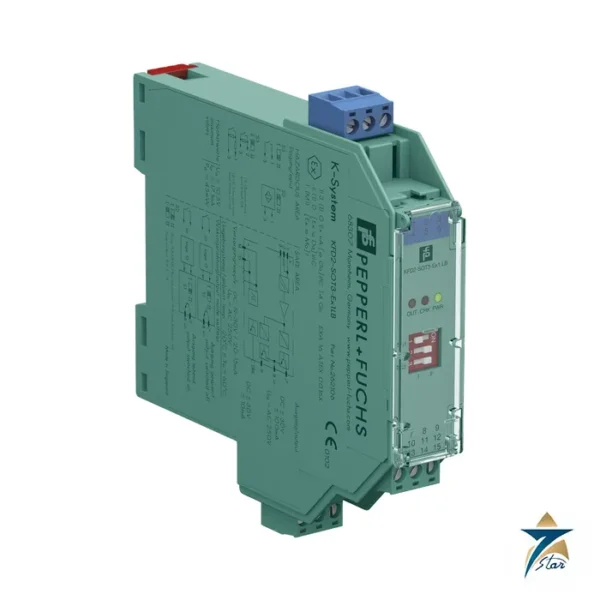
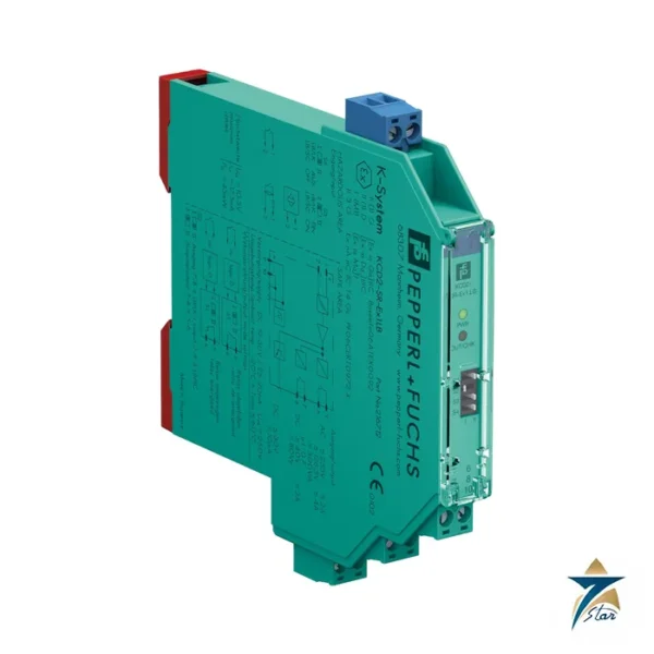
The KFD2-DWB-Ex1.D sits between a proximity sensor on a shaft or gear (for example a NAMUR inductive sensor) and a trip or alarm circuit. Where only a plain on/off signal is required, switch amplifiers such as KFD2-SR2-Ex1.W are simpler. If the speed must be a 4 to 20 mA analog signal, a frequency converter from the same K-System range is the right family; confirm the exact model against its datasheet.
Selection and ordering checklist
- Number of pulses per revolution of the target and the speed range to be monitored.
- Overspeed or underspeed setting and relay action.
- Whether start-up override is needed and how long.
- Relay load against 2 A ratings and voltage.
- Sensor Ex data against Uo 10.1 V, Io 13.5 mA, Po 34 mW.
- Supply 20 to 30 V DC or Power Rail.
Installation, commissioning and maintenance of the KFD2-DWB-Ex1.D
Mount the 40 mm wide module on a DIN rail and wire the sensor to terminals 1+ and 3-. Use the front keypad to enter the reference frequency, then spin the machine or simulate pulses with a frequency generator and confirm the relay thresholds. Record the settings in the loop sheet because they are held in the device only.
Test the start-up override with the machine at standstill, and check that the relay returns to the safe state when the sensor cable is disconnected.
Settings worth documenting for the KFD2-DWB-Ex1.D
Record these items for every KFD2-DWB-Ex1.D in the loop folder: reference frequency, overspeed or underspeed mode, relay energized state, start-up override time, and the number of pulses per revolution of the target. With these notes a replacement unit can be programmed in minutes, and a trip investigation can show whether the set point or the machine caused the event.
Choose relay action so that the safe state corresponds to a de-energized relay, since the relay also drops on a line fault or loss of supply. Remember that response delay of up to 200 ms plus the contact delay of about 20 ms adds to the measuring time, so very fast trips need that budget calculated.
Typical applications in Oman and the GCC
Speed monitoring with the KFD2-DWB-Ex1.D is used on cooling-tower and ventilation fans, pump sets, screw conveyors, gas compressors and turbines in Omani oil, gas, cement and power plants, wherever a NAMUR sensor must be isolated from a Zone 1 or 2 shaft area.
Family comparison
| Part |
Key difference |
| KFD2-DWB-Ex1.D (this part) |
Speed monitor, programmable limits, 2 relays, 40 mm |
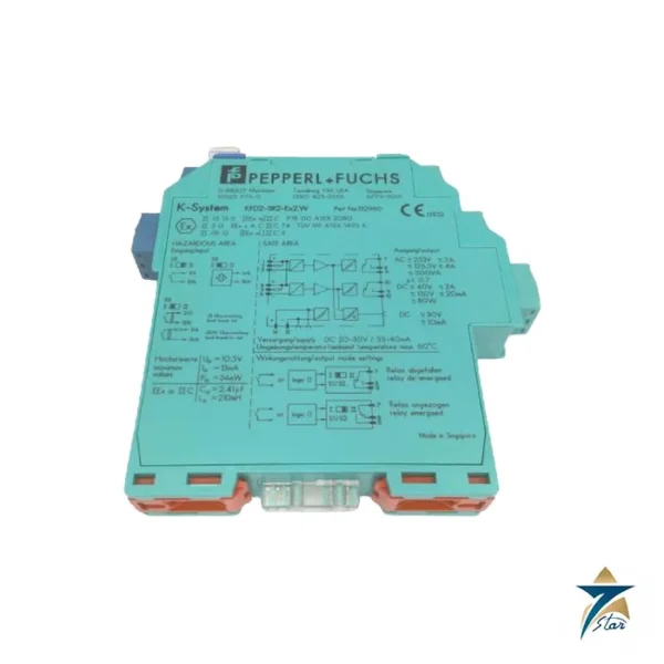
| KFD2-SR2-Ex1.W |
Switch amplifier, 1 relay output |
| KFD2-VR4-Ex1.26 |
Vibration voltage repeater |
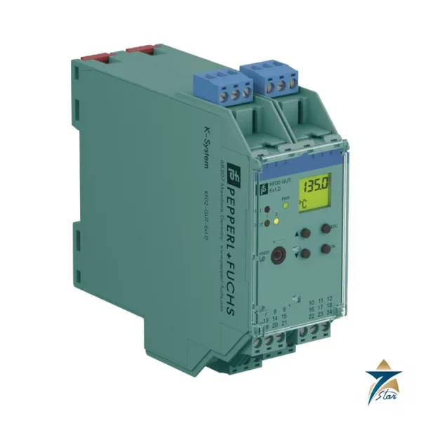
| KFD2-GUT-Ex1.D |
Temperature converter with trip values, 40 mm |
Information to send with an RFQ
- Part number KFD2-DWB-Ex1.D and quantity
- Sensor type and pulses per revolution
- Speed range and limits
- Relay load
- Supply method
- Delivery location
Documents and quotation
The manufacturer datasheet for KFD2-DWB-Ex1.D is attached on this page, so you can check wiring, approvals and dimensions before ordering. Send the exact part number, quantity and delivery location in Oman or the GCC and Seven Star LLC will reply with a quotation.
Seven Star LLC is an independent supplier in Muscat and is not the manufacturer; confirm availability, lead time and any project approval requirements in your RFQ.



















Reviews
There are no reviews yet.