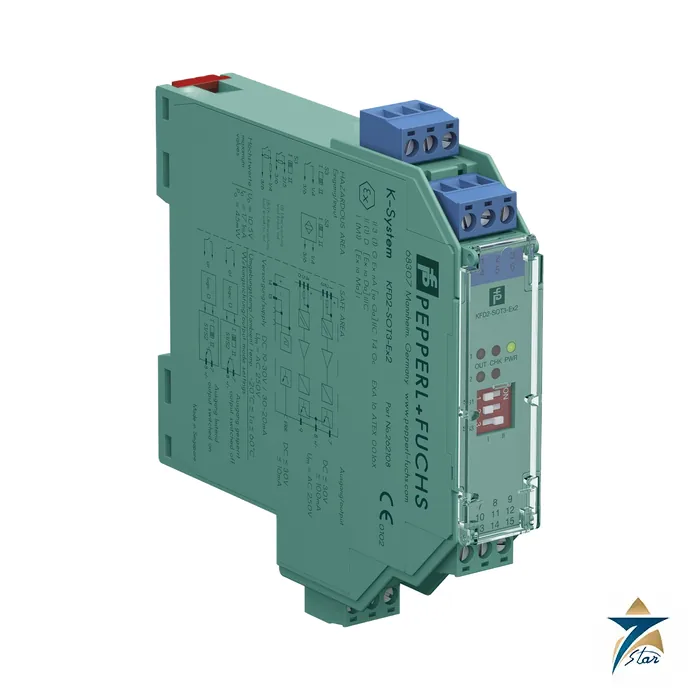
KFD2-SOT3-Ex2 two-channel NAMUR switch amplifier with transistor outputs
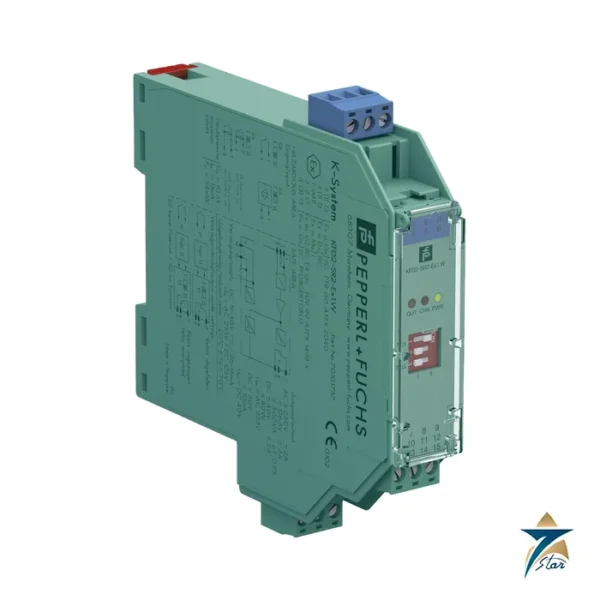
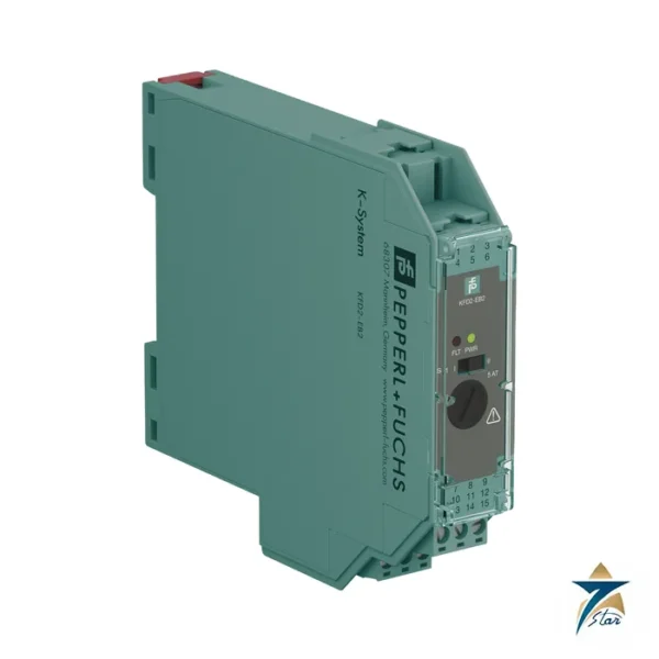
The KFD2-SOT3-Ex2 from Pepperl+Fuchs is a two-channel isolated barrier of the K-System family. It reads two NAMUR proximity sensors or dry contacts located in a hazardous area and repeats each state to the safe area on its own passive transistor output. Supply is 24 V DC, taken either from a Power Rail or from terminals 14+ and 15-, and the housing is a 20 mm wide type B2 module for 35 mm DIN rail.
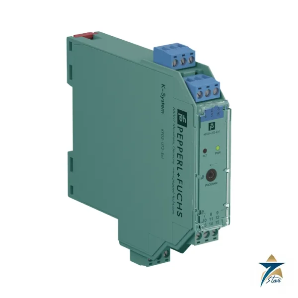
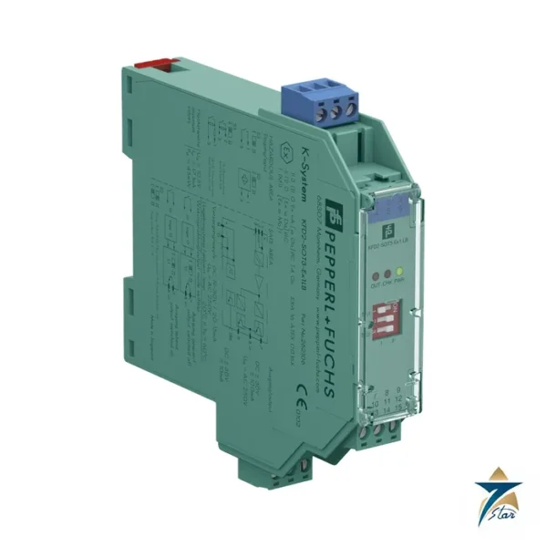
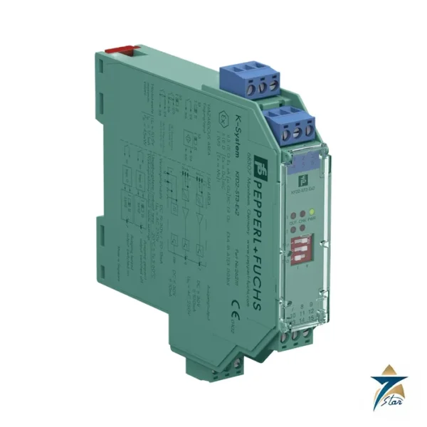
Reading the part number: KFD2 is the 24 V DC K-System isolated barrier line, SOT3 stands for the switch amplifier with transistor output generation 3, and Ex2 means two channels. The sibling KFD2-SOT3-Ex1.LB is the single-channel version, and KFD2-ST3-Ex2 is the two-channel version with active (supply-fed) transistor outputs.
Seven Star LLC supplies this module in Oman and the GCC as an independent supplier in Muscat, for plant teams that need a like-for-like replacement or a new barrier for NAMUR proximity sensors.
Technical specifications of the KFD2-SOT3-Ex2
| Parameter |
Specification |
| Manufacturer / part number |
Pepperl+Fuchs KFD2-SOT3-Ex2 |
| Channels |
2 |
| Input |
Dry contact or NAMUR sensor, acc. to EN 60947-5-6 |
| Open circuit voltage / short-circuit current |
approx. 10 V DC / approx. 8 mA |
| Switching point / hysteresis |
1.2 to 2.1 mA / approx. 0.2 mA |
| Line fault detection |
Breakage I ≤ 0.1 mA, short-circuit I ≥ 6.5 mA |
| Output |
2 passive transistor outputs, 30 V DC, 100 mA, short-circuit protected |
| Signal level |
Off state leakage ≤ 10 µA; saturation drop about 3 V at 100 mA |
| Response time / switching frequency |
≤ 200 µs / ≤ 5 kHz |
| Supply |
19 to 30 V DC via Power Rail or terminals 14+/15-; power dissipation ≤ 1.1 W including output dissipation |
| Functional safety |
SIL 2, systematic capability SC 3 acc. to IEC/EN 61508 |
| Hazardous area data |
Ex ia input, Uo 10.5 V, Io 17.1 mA, Po 45 mW; marking II 3(1)G Ex nA [ia Ga] IIC T4 Gc; EXA 16 ATEX 0016 X |
| Ambient temperature |
-20 to 60 °C |
| Housing |
Type B2, 20 x 119 x 115 mm, IP20, screw terminals, approx. 150 g |
How the barrier works
Each channel of the KFD2-SOT3-Ex2 supplies a NAMUR sensor with roughly 10 V through a resistor network and watches the loop current. A current in the 1.2 to 2.1 mA band marks the switching point, with about 0.2 mA of hysteresis, so a normal sensor swings between roughly 1 mA and 3 mA or more as the target approaches. The input circuit is intrinsically safe: its energy is limited to the Ex ia values listed above, and it is separated from the safe side by reinforced insulation rated for 300 Veff under IEC/EN 61010-1.
Line fault detection watches for a broken cable (current below 0.1 mA) or a shorted cable (above 6.5 mA). When a fault occurs the front LED shows it as described in NAMUR NE44 and the shared fault line to the Power Rail is raised, so a bus-level alarm can be wired without separate cabling. Three DIP switches on the front of the KFD2-SOT3-Ex2 reverse the output action for each channel and disable line fault detection where a plain dry contact without end-of-line resistors is connected.
The two outputs of the KFD2-SOT3-Ex2 are passive transistors: the control system supplies the voltage and the module simply conducts or blocks, which suits PLC inputs that source their own 24 V. This is the key difference from the KFD2-ST3-Ex2, whose outputs take their voltage from the module supply.
Where the KFD2-SOT3-Ex2 fits in the system
Typical field devices are NAMUR proximity switches (for example valve position feedback, cam and limit detection), mechanical limit switches and pushbuttons fitted with the resistor pair shown on the wiring diagram (400 Ω to 2 kΩ series and 10 kΩ parallel), and any other contact that must be isolated from a Zone 0, 1 or 2 area. The module itself is installed in the safe area or in Zone 2, which is covered by its Ex nA [ia Ga] marking.
Related parts in the same family are KFD2-SOT3-Ex1.LB, KFD2-ST3-Ex2 and KFD2-SR2-Ex2.W (relay outputs). On a Power Rail the supply and the collective error message travel through the rail, so the modules clip together without individual 24 V wiring.
Selection and ordering checklist for KFD2-SOT3-Ex2
- Confirm that the field device is a NAMUR sensor or a contact with the standard resistor network; 3-wire PNP/NPN sensors are not suitable.
- Check that the PLC input accepts a passive transistor output: external supply up to 30 V DC, load up to 100 mA, with about 3 V drop at full load.
- Decide whether each channel should operate normally or in reversed mode and note the DIP setting needed.
- Check that the Ex ia values of the sensor (Ui, Ii, Pi, Ci, Li) are compatible with Uo 10.5 V, Io 17.1 mA and Po 45 mW and the permitted cable capacitance and inductance.
- Verify the installation location against the Ex nA [ia Ga] marking and the local rules for Zone 2.
- Choose a Power Rail or separate 24 V terminals depending on the panel layout.
Installation, commissioning and maintenance
Snap the KFD2-SOT3-Ex2 onto a 35 mm DIN rail in a clean enclosure at -20 to 60 °C, keep the blue Ex terminals separated from the safe-area terminals as the manufacturer requires, and wire according to the diagram on the datasheet. Set the three DIP switches before power-up; the label strip on the front takes the tag numbers.
For commissioning, bridge each input with a short and then open it while watching the OUT and CHK LEDs: a lit CHK LED must appear for both conditions when line fault detection is active. Check the output state at the PLC card and confirm that the shared fault output reaches the control system. In service the KFD2-SOT3-Ex2 needs no adjustment; periodic proof testing should follow the plant SIL procedure, and spare modules should be kept dry and in their original packing.
Typical applications in Oman and the GCC
Two-channel NAMUR barriers such as the KFD2-SOT3-Ex2 are common on oil and gas wellheads, manifold valve boxes, tank farm switches and pump packages in Oman, where proximity sensors report open or closed positions into remote I/O cabinets. The same module fits desalination chemical dosing skids, gas turbine auxiliaries and petrochemical units across the GCC. Cabinets are often in hot, dusty shelters, so margin on the 60 °C limit and a clean enclosure are worth planning for.
Family comparison
| Part |
Key difference |
| KFD2-SOT3-Ex2 (this part) |
2 channels, 2 passive transistor outputs, SIL 2 |
| KFD2-SOT3-Ex1.LB |
1 channel, 2 passive outputs (second selectable as fault output) |
| KFD2-ST3-Ex2 |
2 channels, active transistor outputs |
| KFD2-SR2-Ex2.W |
2 channels, relay outputs |
Information to send with an RFQ
- Part number KFD2-SOT3-Ex2 and quantity
- Sensor type and manufacturer data (NAMUR or contact)
- PLC input type and voltage
- Hazardous area zone and gas group
- Power Rail or discrete supply
- Delivery location in Oman or the GCC
Documents and quotation
The manufacturer datasheet for KFD2-SOT3-Ex2 is attached on this page, so you can check wiring, approvals and dimensions before ordering. Send the exact part number, quantity and delivery location in Oman or the GCC and Seven Star LLC will reply with a quotation.
Seven Star LLC is an independent supplier in Muscat and is not the manufacturer; confirm availability, lead time and any project approval requirements in your RFQ.
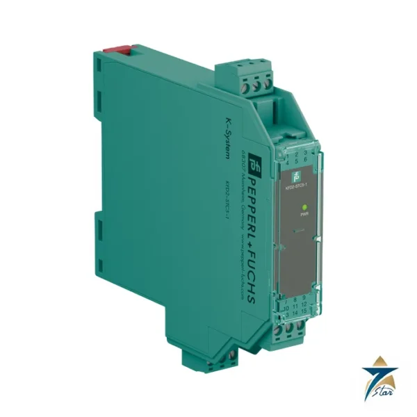
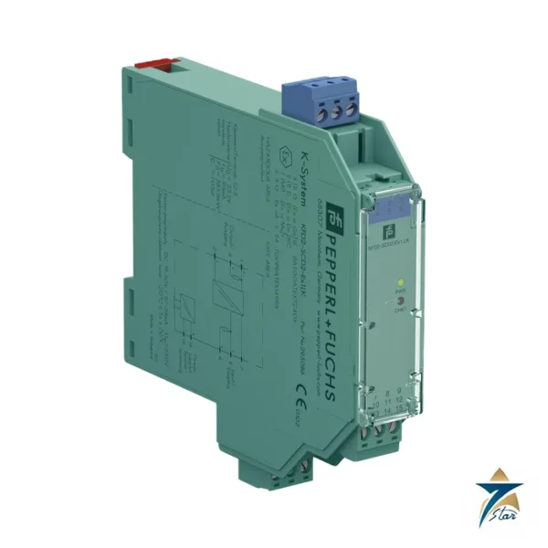
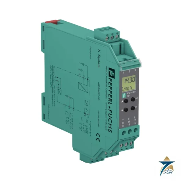
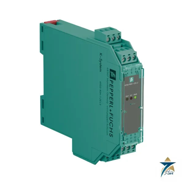
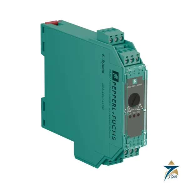
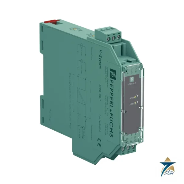
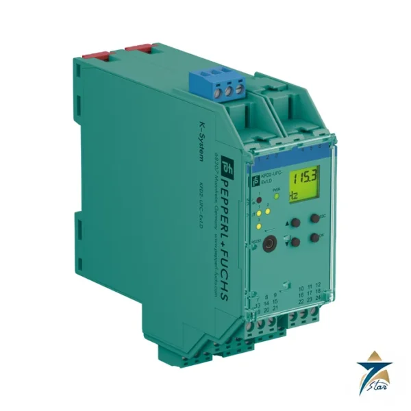
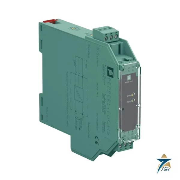
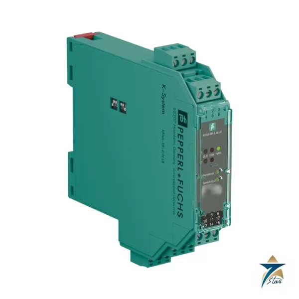
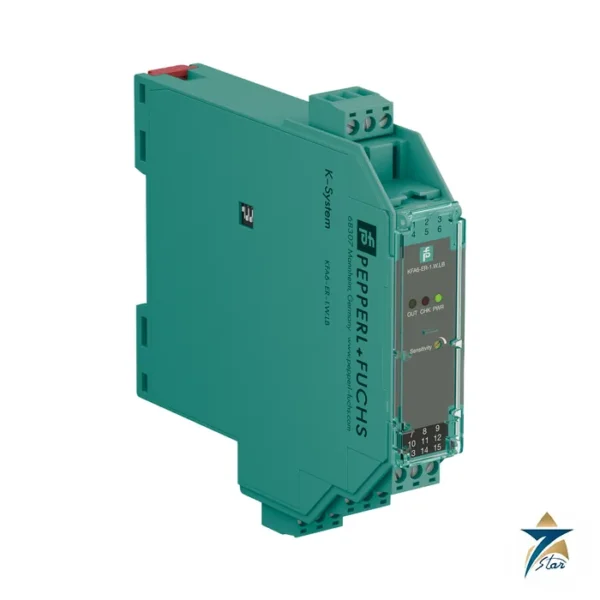
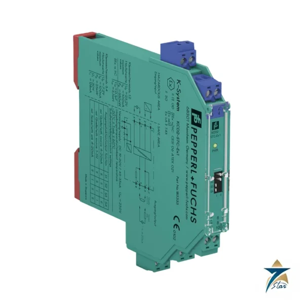
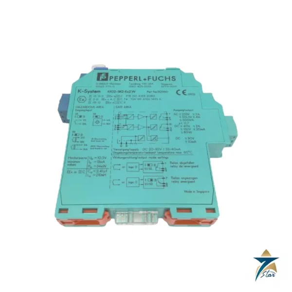
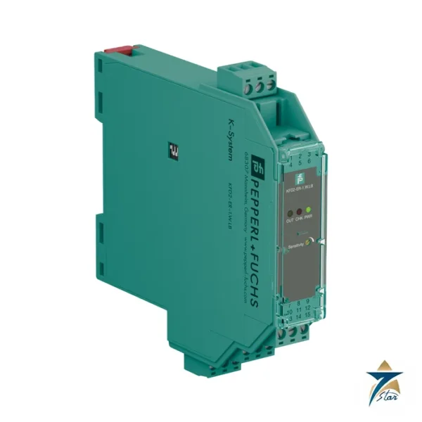
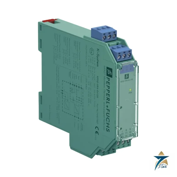
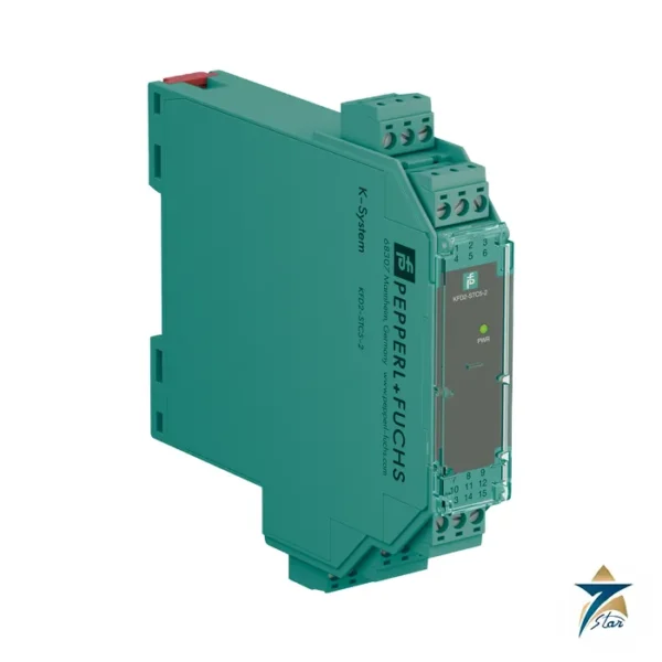
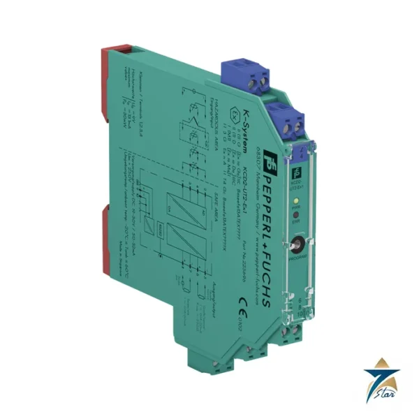
Other Models in the Pf Kfd2 Sot3 Range
Seven Star LLC supplies models from the Pf Kfd2 Sot3 range in Oman and the GCC. Compare the related models below and request a quote for the one that matches your application.



















Reviews
There are no reviews yet.