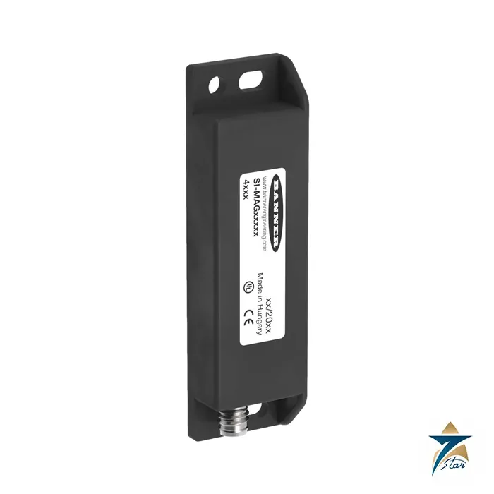
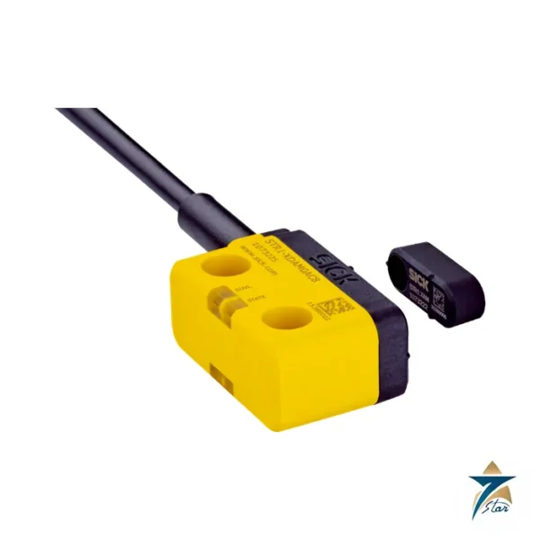
A coded non-contact magnetic door sensor with a 4-pin M8 connector
The SI-MAGB1SMQD is the sensor half of Banner Engineering’s SI-MAG non-contact magnetic safety interlock system: a two-piece coded magnetic safeguarding device in a compact rectangular polyamide housing with an integral 4-pin M8 quick-disconnect. One sensor and one coded magnet correctly placed on a guard door can reach the highest levels of safety (control reliable, Category 4, PL e or SIL CL 3) when monitored by a suitable safety monitoring module.
Coded magnets minimise the risk of intentional defeat. The sensor contains three pole-stable reed switches, and the circuit is epoxy-encapsulated in a PA 6 housing rated IP67.
Technical specifications
| Parameter |
Specification |
| Model |
SI-MAGB1SMQD sensor with 4-pin M8 QD (matching coded magnet SI-MAGB1MM, 4 mm to 14 mm switching distance) |
| Switching elements |
Three pole-stable reed switches |
| Safety rating |
B10d 20 million cycles at 20 % load; 0.4 x 10^6 cycles at nominal load per ISO 13849-1; mission time 20 years |
| Maximum switching |
60 V AC / 30 V DC; 0.08 A; 0.25 VA |
| Repeat switching accuracy |
0.1 x switching distance, same geometry and temperature |
| Mechanical life |
3 x 10^8 cycles, depending on load resetability |
| Operating frequency |
1 Hz |
| Construction |
Epoxy-encapsulated circuit in polyamide (PA 6) housing |
| Environmental rating |
IP67 per IEC 529 (EN 60529) |
| Operating temperature |
-25 degrees C to +70 degrees C; below -5 degrees C the cable must be fixed |
| Pollution degree |
3 per EN 60947-1 |
| Connection |
4-pin M8 quick-disconnect; cable versions use a 3 m 26 AWG 4-wire PVC cable |
| Listing printed |
Ind Control Equipment / Class 2 Power Source Listed 4VZ3 (as printed) |
The SI-MAG family at a glance
The manual covers three housings. The B1 series is the rectangular style: SI-MAGB1SM (cable), SI-MAGB1SMCO (cable opposite), SI-MAGB1SMQD (M8 connector) and SI-MAGB1SMCOQD (M8 connector opposite). The B2 style is a small cylindrical sensor (3 mm to 14 mm) and the B3 an M30 barrel (5 mm to 14 mm). Matching magnets are SI-MAGB1MM, the 90 degree SI-MAGB1MM90 and the 8 mm to 16 mm SI-MAGB1MMHF.
Older models without the B in the model name are non-UL approved and do not work with SI-MAGB models.
System requirements and ordering
A basic SI-MAG system needs the sensor, a coded magnet, a mating cable for QD versions and a safety monitoring device. The manual states that the user is responsible for complying with all local, state and national laws and codes, and that a basic system includes a safety monitoring device.
Order the sensor and magnet together, check the connector style and cable length, and confirm the safety module input compatibility before purchase.
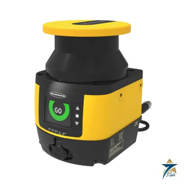
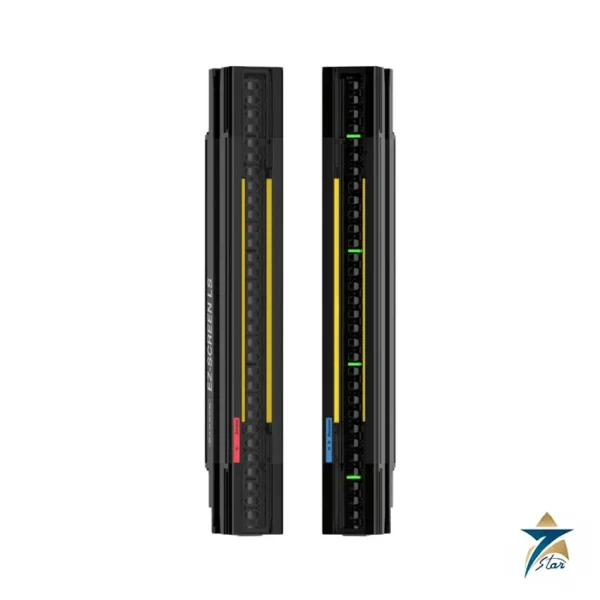
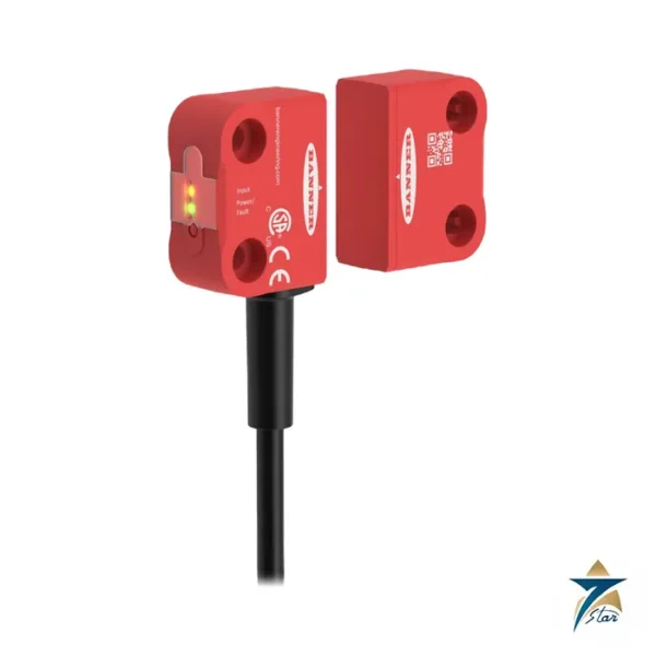
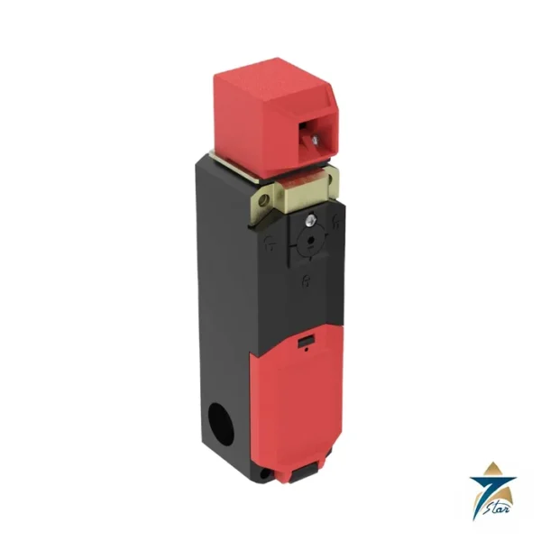
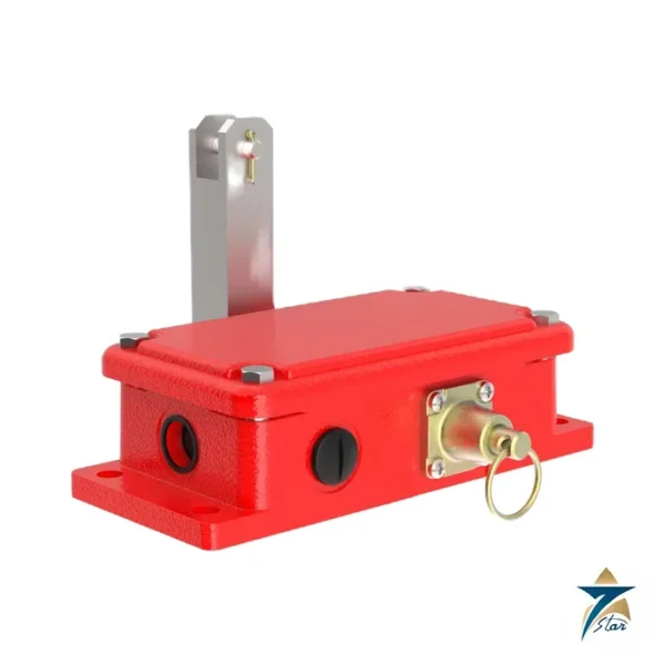
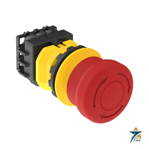
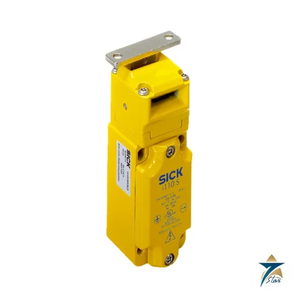
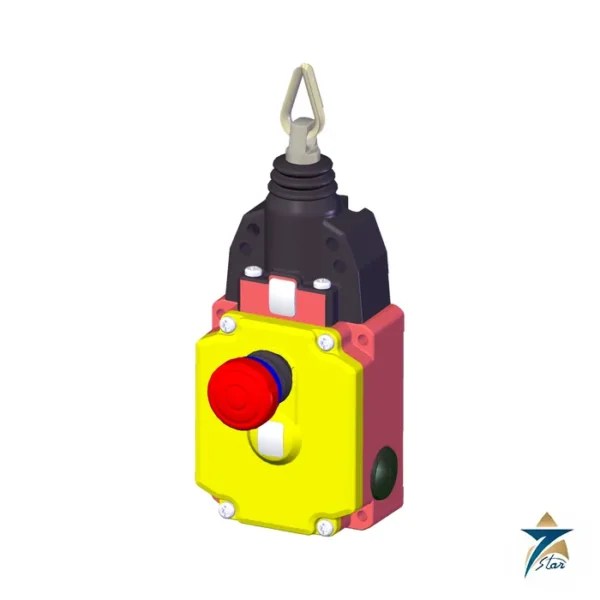
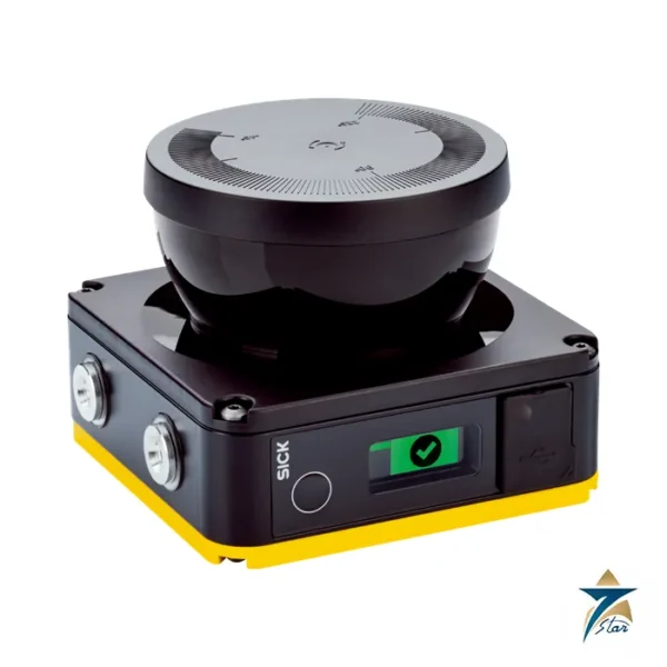
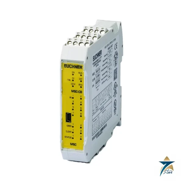
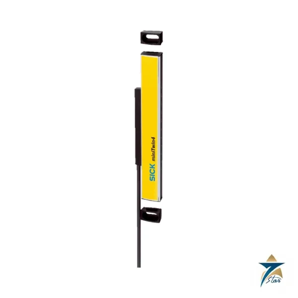
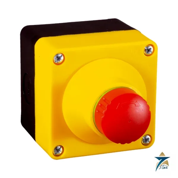
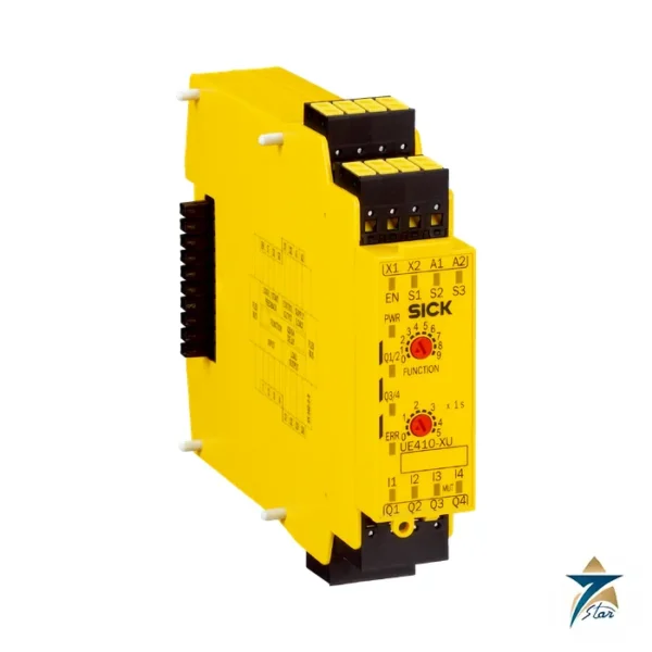
Related Banner Engineering products: Banner SI-LS42 Locking Safety Interlock Switch, Banner SI-RF Non-Contact RF Safety Switch, Cat 4 PL e, Banner SX5 Safety Laser Scanner, 5.5 m Type 3 PL d, Banner EZ-SCREEN LS Type 4 Safety Light Curtain, Banner RP-QM90F-100L Rope Pull Emergency Stop Switch and Banner SSA-EB1P-02 Emergency Stop Push Button, 40 mm.
How the SI-MAG switch works
Banner’s instruction manual describes the SI-MAG as a magnetically operated position switch based on reed contact technology. The switching function is triggered when the coded permanent magnet approaches the active face or side of the sensor. The operating distance depends on the size, strength and direction of the actuating magnet and on the sensitivity of the reed contacts. Because there is no mechanical tongue or plunger, the sensor and magnet can be fully enclosed, which suits guards that are washed down or exposed to dust. The contacts are low power: Banner gives a maximum switching voltage of 60 V AC / 30 V DC, a maximum switching current of 0.08 A and a maximum switching capacity of 0.25 VA, so the switch must be connected to a suitable safety monitoring device rather than switching a load directly.
Installation requirements from the manual
Banner refers to ANSI B11.19, or ISO 14119 and ISO 14120, for interlocked guards. The key requirements are:
- The hazard must not be able to operate until the guard is closed, and a stop command must be issued if the guard opens while the hazard is present. Closing the guard must not, by itself, start hazardous motion.
- The guard must be placed far enough from the danger zone that the hazard stops before a person can reach it.
- Do not use the safety switch as a mechanical or end-of-travel stop; limit the movement of the guard so the switch and actuator cannot be damaged.
- Mount the switch and magnet at least 15 mm (0.6 in) from any magnetized or ferrous material, since iron mounting surfaces affect the switching distance.
- The 4.5 mm mounting holes accept M4 (#6) hardware. Banner recommends avoiding ferromagnetic screws where possible and using permanent fasteners or locking hardware so the position cannot change after adjustment.
- Install the switch so it cannot be easily defeated, keep it accessible for functional checks, and do not use it within known fields of high-level electromagnetic radiation.
Banner also warns about pass-through hazards in perimeter guarding, where a person could walk through the guard and be inside the area when the machine restarts; ANSI B11.19, ANSI B11.20 or ISO 11161 should be consulted for these cases.
Documents and quotation
Please check the coded magnet, mating cable and safety module before ordering, because the final code depends on the installation. The attached manufacturer file, Banner SI-MAG Non-Contact Magnetic Safety Interlock Switch instruction manual, p/n 210255 (manufacturer, unaltered), carries the authoritative data. Send the code you selected and the quantity, and we respond with a written offer. Similar instruments: Safety Switches & Guard Locking.


















Reviews
There are no reviews yet.