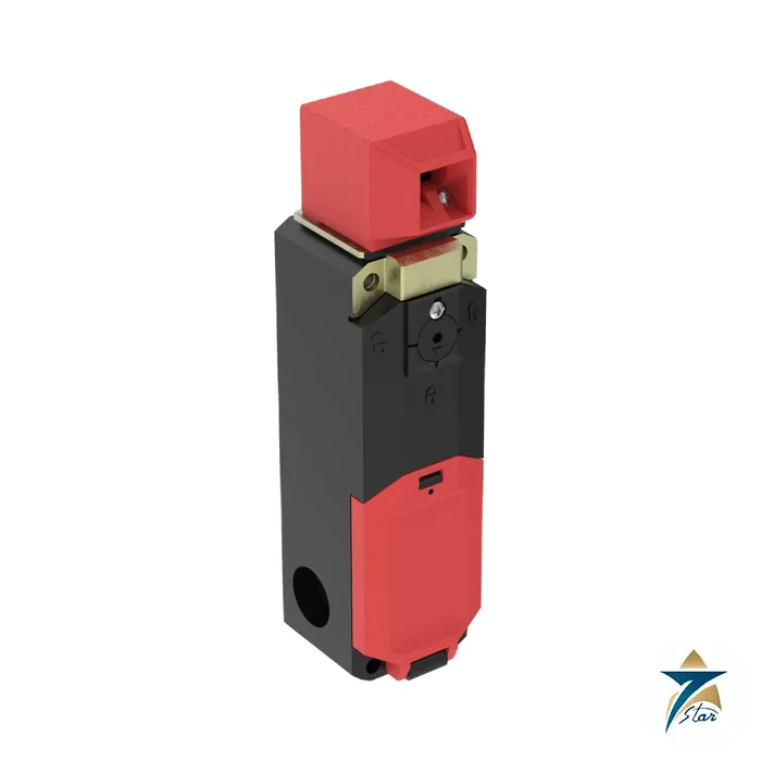
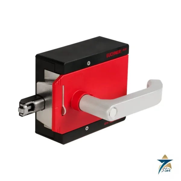
The Banner SI-LS42 is a locking-style safety interlock switch that both monitors a guard and holds it shut until the hazard has stopped. It is used on gates and doors of robot cells, presses, packaging machines and any guard that must stay closed while a machine coasts down.
A choice of spring-lock and solenoid-lock styles, two solenoid voltages, four contact arrangements and two actuator types gives many ordering combinations. Seven Star LLC, an independent supplier in Muscat, quotes SI-LS42 interlocks and actuators by exact model code from the Banner instruction manual.
Technical specifications
| Parameter |
Specification |
| Type |
Guard-locking safety interlock switch with positive opening contacts (IEC 60947-5-1); type 2 locking device with low-level coding per ISO 14119 |
| Locking styles |
Spring lock with solenoid unlock (models SI-LS42xMS and xWMS, with manual release) or solenoid lock with spring unlock (SI-LS42xMM) |
| Solenoid voltage |
24 V AC/DC (-15 %/+10 %) or 110/230 V AC (-15 %/+10 %) |
| Solenoid power |
24 V: 12 VA inrush for 0.2 s, 4.4 VA continuous; 110/230 V: 65 VA inrush for 0.1 s, 8 VA continuous |
| Contact configurations |
1 NC + 1 NO, 2 NC, 2 NC + 1 NO or 3 NC with the actuator engaged, plus solenoid monitor contacts |
| Actuators |
Stainless steel rigid in-line (SI-QM-SSA) or flexible in-line (SI-QM-SMFA); head rotates in 90 degree steps |
| Contact rating |
AC-15, 230 V / 2.5 A; thermal current 5 A; silver-nickel contacts; B300 pilot duty (same polarity) |
| Mechanical life |
1 x 10^6 switching cycles; B10d 2 x 10^6 cycles (NC contacts, DC-13, 24 V, 0.1 A) |
| Actuator force and speed |
Extraction force up to 1500 N when locked (GS-ET-19); maximum actuator speed 0.5 m/s |
| Minimum actuator radius |
400 mm for in-line actuators; 150 mm for flexible actuators |
| Connections |
10 spring-clamp terminals, 0.5 to 1.5 mm2; three M20 x 1.5 cable entries with 1/2 in NPT adapter |
| Enclosure and conditions |
Glass-fibre thermoplastic housing, IP67 with suitable screw; -25 to +70 C; class II double insulated; about 0.34 kg |
Choosing the locking style
With spring lock and solenoid unlock (SI-LS42xMS and xWMS) the actuator is locked mechanically when fully inserted and released by applying voltage to the solenoid; these models include a manual release. With solenoid lock and spring unlock (SI-LS42xMM) the actuator is locked when voltage is applied and released when voltage is removed. The manual shows the model number with an S or M inserted in the position marked by the underscore, for example SI-LS42DM_G becomes SI-LS42DMSG or SI-LS42DMMG.
Contacts, actuators and monitoring
The contact monitors both the presence of the actuator and whether it is locked. The four contact configurations give normally closed safety contacts with positive opening action and additional contacts for the lock monitor. The rigid in-line actuator suits straight-closing guards, and the flexible in-line actuator tolerates more door movement, with the minimum engagement radius of 150 mm for flexible actuators. The actuator head can be rotated in 90 degree increments for horizontal or vertical actuation.
Installation and what to confirm
A complete safety system typically uses two interlocks, two actuators, two cables and a safety monitoring device, and the manual states that the switch must not be used as a mechanical or end-of-travel stop. Browse the safety switches and guard locking category for related devices. Please confirm before ordering: locking style, solenoid voltage, contact configuration, actuator type, cable entry, and the safety relay or controller used to monitor it.
Key features
- Guard locking up to 1500 N: the locked actuator resists high extraction forces, so a door cannot be pulled open while a robot, spindle or flywheel is still moving.
- Positive opening contacts: the normally closed safety contacts are forced open mechanically to IEC 60947-5-1, even if a contact welds.
- Lock monitoring: separate contacts report whether the solenoid lock is engaged, allowing the safety controller to confirm both door position and lock state.
- Flexible mounting: the head turns in 90 degree steps and three M20 entries give several cable routing options.
- Spring-clamp terminals: ten terminals for 0.5 to 1.5 mm² conductors speed up wiring and resist vibration loosening.
Spring lock or solenoid lock: safety considerations
The choice of locking principle affects both safety and availability. A spring-lock (power-to-unlock) switch keeps the guard locked during a power failure, which is the usual choice when hazardous motion can continue after power is lost, such as a coasting saw blade or a heavy rotating drum. The manual release on these models allows a trapped operator or a maintenance technician to open the guard in an emergency.
A solenoid-lock (power-to-lock) switch releases the guard when power is removed. It is often used for process protection, where the lock prevents an operator from interrupting a cycle, but where no dangerous run-down exists. A risk assessment to ISO 12100, together with ISO 14119 guidance on interlocking devices, should determine which principle is acceptable.
Integration with a safety controller
The switch is one element of a safety function. To reach the required performance level, the contacts are typically wired in two channels to a safety relay or safety PLC that monitors for cross faults and discrepancy. The unlock request should be released only after a standstill monitor, a safe timer or the machine control confirms that the hazard has stopped. Banner safety controllers and safety relays are designed to evaluate this type of dual-channel input, but other monitored safety devices can be used if they meet the required category.
Reducing defeat risk
As a low-level-coded device per ISO 14119, the switch should be mounted so that it is difficult to bypass with a spare actuator. Use tamper-resistant fasteners, keep spare actuators under control and, where possible, position the switch so it is concealed or protected behind the guard frame.
Installation and maintenance practice
- Align the actuator so it enters the head centrally; observe the minimum radii of 400 mm (rigid) and 150 mm (flexible) for hinged doors.
- Fit a separate mechanical stop for the door, as the switch must not act as an end stop.
- Seal unused cable entries to keep the IP67 rating.
- Check function, fastener tightness and actuator wear at the intervals defined by the machine’s maintenance plan, and replace the switch before its B10d-based lifetime is reached in high-cycle applications.
Use in Gulf industrial plants
The thermoplastic housing and the -25 to +70 °C range suit food and beverage lines, bottling plants, packaging halls and metalworking shops across Oman and the GCC. On machines with washdown or high dust levels, choose suitably sealed cable glands and route cables from below to keep moisture away from the entries.
What to send with your RFQ
- Full model code with locking style (S or M), solenoid voltage and contact configuration.
- Actuator type and quantity, including spares.
- Required cable entry adapters and the safety relay or controller to be used.
Documents and quotation
The attached file is the unaltered official SI-LS42 Series Locking-Style Safety Interlock Switch Instruction Manual, p/n 155400 Rev. H, dated 22 July 2024. Seven Star LLC supplies the exact model code you specify and confirms availability and lead time in the quotation. Send the model code, quantity and delivery location to our team and we will respond with a price.



Reviews
There are no reviews yet.