A Category 4 E-stop safety module with three normally open outputs
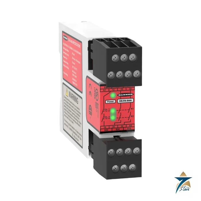
The ES-FA-9AA is Banner Engineering’s two-channel emergency stop safety module with three normally open output channels, each a series connection of contacts from two forced-guided (mechanically linked) relays K1 and K2. It is designed to monitor emergency stop buttons and rope pull switches and to meet Category 4 PL e per EN ISO 13849-1 and SIL 3 per IEC 61508 when correctly wired.
Three green LEDs show power, K1 and K2 energised. The module mounts on 35 mm DIN rail inside an enclosure rated NEMA 3 (IEC IP54) or better, and supports automatic reset or monitored manual reset depending on the hook-up.
Technical specifications
| Parameter |
Specification |
| Model |
ES-FA-9AA: 3 N.O. outputs, 6 A; the ES-FA-11AA gives 2 N.O. plus 1 N.C. auxiliary, 7 A |
| Supply |
24 V DC plus or minus 10 % (SELV) or 24 V AC plus or minus 10 %, 50/60 Hz; about 2 W / 2 VA |
| Safety integrity |
Category 4 PL e per EN ISO 13849-1; SIL 3 per IEC 61508 (as printed in manual) |
| Output contacts |
AgNi, 5 um gold plated; N.O. channels are series contacts of forced-guided relays K1-K2 |
| Low-current rating |
1 V to 60 V; 5 mA to 300 mA; 5 mW to 7 W |
| High-current rating |
15 V to 250 V AC/DC; 30 mA to 6 A (200 W, 1500 VA) |
| Output response time |
25 milliseconds typical |
| Mechanical / electrical life |
Over 20,000,000 operations / 150,000 cycles at 1500 VA, 1,000,000 at 450 VA |
| Input requirements |
Dual-channel contact wiring; reset switch 20 mA at 12 V DC, hard contact only |
| Construction |
Polycarbonate housing; NEMA 1, IEC IP40; terminals IP20 |
| Operating conditions |
0 degrees C to +50 degrees C; 90 % at +50 degrees C, non-condensing |
| Terminal torque / wire |
0.8 N-m; 1 x 2.5 mm2 stranded ferruled, 1 x 4 mm2 solid, 2 x 1.5 mm2 stranded ferruled |
Where this module sits in a safety circuit
Applicable standards listed in the manual include ISO 12100, ISO 13849-1, ISO 13850 (EN 418) and EN 60204-1, plus ANSI B11 and NFPA 79 for the US. The module increases the integrity of the E-stop circuit; two redundant relays must both drop out, and the monitoring detects failures before the next demand.
Gold-plated contacts allow low-current switching, but once a contact has switched higher loads the low-level rating should not be reused, so the manual asks the designer to preserve the plating by keeping within the stated maximum values.
Ordering and installation notes
The datasheet-style choice is between the ES-FA-9AA with three N.O. outputs and the ES-FA-11AA with an extra N.C. auxiliary monitoring output. Transient suppressors should be fitted across inductive loads, never across the output contacts. Output contacts at 151 V to 250 V AC/DC are overvoltage category III only when appropriate overvoltage reduction is provided.
Confirm supply voltage, reset method and the number of outputs before ordering; wiring and validation remain the responsibility of the installer.
Key features of the ES-FA-9AA
- Redundant forced-guided relays – two mechanically linked relays switch every safety output in series, so a single welded contact cannot leave the hazard energised.
- Self-monitoring – the module checks its own relays and the input channels at each cycle and will not reset if a fault is present.
- Three safety outputs – enough to interrupt several contactors or control circuits, for example a main motor contactor, a hydraulic valve and a second drive enable.
- Flexible reset – automatic or monitored manual reset, selected by wiring, to suit the risk assessment of the machine.
- AC or DC supply – one model can be used on 24 V DC or 24 V AC control circuits.
- Compact DIN-rail housing – fits standard control panels alongside other safety and control components.
Designing the E-stop circuit
A safety module only delivers its rated performance level when the whole safety function is designed correctly. The input devices – emergency stop buttons or rope pull switches – should have two positively opening contacts wired to the two input channels. The output side should use contactors or other devices with mechanically linked or mirror contacts, and those feedback contacts should be wired into the module’s monitoring or reset loop so that a welded output contactor is detected. Cable routing should protect against short circuits between channels, especially where wiring leaves the panel.
Choosing the reset mode
Monitored manual reset is the usual choice for emergency stop functions, because the machine should not restart by itself when the E-stop button is released. The reset button must be located where the operator can see the hazardous area. Automatic reset is generally only appropriate where another device, such as a downstream control, provides the deliberate restart action.
Installation and periodic testing
- Install the module in an enclosure with the protection rating stated in the manual and keep it away from heat sources.
- Fit suitable arc suppression across inductive loads switched by the output contacts, as described in the manual, and do not place suppressors directly across the safety contacts in a way that could hide a fault.
- Fuse the output contacts appropriately to protect them from overcurrent and welding.
- Test each E-stop device and the complete stopping function at commissioning and at the intervals required by the machine’s risk assessment.
- Keep wiring diagrams and test records with the machine documentation.
Use in Oman and GCC plants
Conveyor systems in mining and cement plants, packaging lines in food factories and machine tools in fabrication workshops across Oman all rely on reliable emergency stop circuits. Long conveyors often combine pull-cord switches with panel-mounted E-stop buttons, and a three-output module can switch several motor contactors from one safety function. Panels in hot plant rooms should be ventilated so internal temperatures stay within the module’s operating range, because relay life and plastic housings both suffer from sustained heat. Dust-tight enclosures reduce contact contamination in quarry and cement environments.
What to include in your RFQ
Specify ES-FA-9AA or the ES-FA-11AA if an auxiliary N.C. output is needed, the quantity and the supply voltage used in your panel. If the module replaces an existing unit, give the model on the label and a short description of the input devices and loads. Ask for the instruction manual with the order if your site requires it for safety documentation.
Documents and quotation
Quote requests are handled from this page: attach your tag list or the full code, and note the supply voltage, reset method and output configuration. The attached PDF (Banner ES-FA-9AA and ES-FA-11AA E-Stop Safety Module product manual, p/n 60606 (manufacturer, unaltered)) is the reference for every value above, and it should be checked again for the final configuration. See also PLC & I/O Cards.









Reviews
There are no reviews yet.