A one-piece wiring base for POINT I/O modules
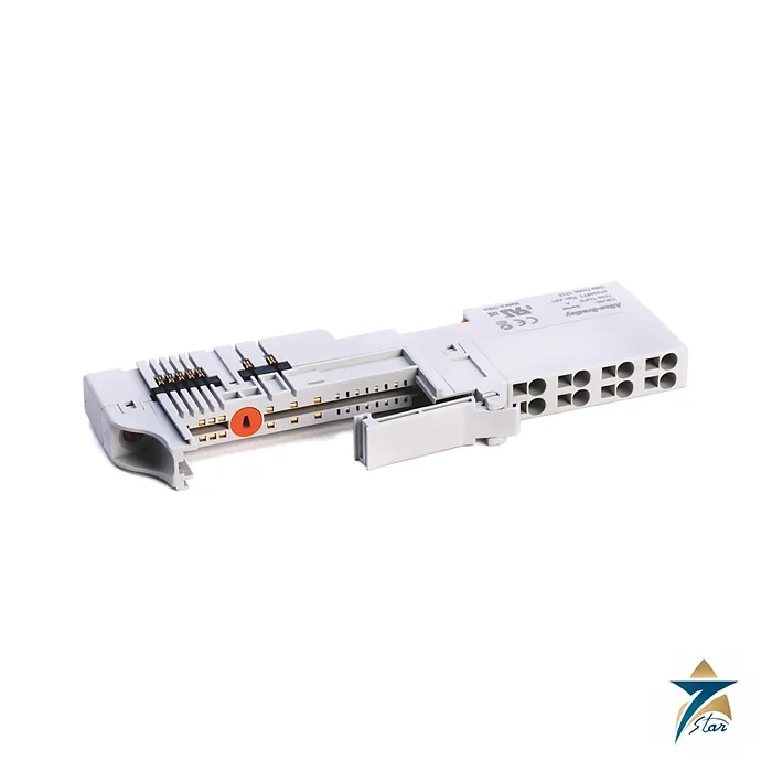
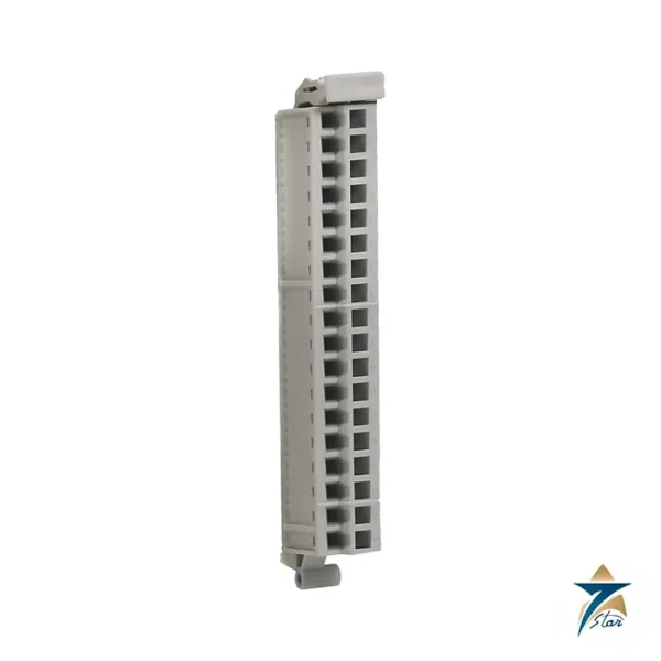
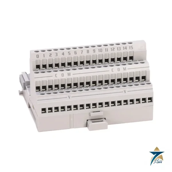
The Allen-Bradley 1734-TOPS is the one-piece spring-clamp wiring base for POINT I/O modules. It combines the mounting base and the removable terminal block in a single part, so each I/O module plugs into a 12 mm wide base that carries the field wiring. The S suffix indicates spring-clamp terminals, which make tool-assisted but screw-free connections and resist loosening under vibration.
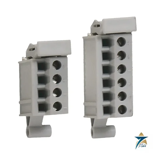
The wiring block has eight terminals in the 1734-TOP and 1734-TOPS styles, with the 1734-TOP3 and 1734-TOP3S providing a 12-position block for modules that need a third wire per point. The base passes the POINTBus backplane signals and the internal field power bus along the node.
Technical specifications
| Parameter |
Specification |
| Catalog number |
1734-TOPS (spring clamp). Related: 1734-TOP screw version, 1734-TOP3 and 1734-TOP3S three-wire versions |
| Type |
POINT I/O one-piece wiring base (terminal base) with spring-clamp wiring |
| Wiring block |
8-position (1734-TOP, 1734-TOPS); 12-position for 1734-TOP3, 1734-TOP3S |
| Wire size without ferrule |
0.25…2.5 mm² (24…14 AWG), one wire; strip length 12 mm (0.47 in.) |
| Wire size with ferrule |
0.50…0.75 mm² (20…18 AWG): strip 14 mm; 1.0…1.5 mm² (17…16 AWG): strip 15 mm |
| Wires per terminal |
Do not wire more than 2 conductors on any single terminal |
| Field power bus supply voltage |
28.8V DC; 120/240V AC |
| Field power bus current, max |
10 A |
| Signal terminal voltage / current |
28.8V DC or 120/240V AC; 2 A |
| Isolation |
Capable of 240V continuous, reinforced insulation, or the lesser rating of the installed module |
| Dimensions |
49 x 12 x 144 mm (1.93 x 0.47 x 5.67 in.) for the 1734-TOPS |
| Weight |
55.68 g (1.96 oz) for the 1734-TOPS; 63.8 g for the 1734-TOP |
| DIN rail |
199-DR1; 46277-3; EN 50022; locked with an orange DIN rail locking screw |
| Enclosure type rating |
None (open style) |
| Surrounding air temperature |
-20…+55 °C (-4…+131 °F) |
| Certifications (as printed) |
CE (LVD EN 61131-2, RoHS EN IEC 63000), UKCA, Morocco; see rok.auto/certifications |
Wiring a spring-clamp base
Strip single wires 12 mm, or 14 to 15 mm when using ferrules, and insert them without a ferrule only if the wire is within the 0.25 to 2.5 square millimetre range. To latch and unlatch a spring clamp the manufacturer says to insert a bladed screwdriver of 3 mm blade (catalog number 1492-N90) into the opening at about 97 degrees and press in, not up or down. Never place more than two conductors in one terminal.
Fit the base on a 35 mm DIN rail first, lock it with the orange DIN rail screw, and only then install the I/O module. The base should not be removed or replaced with power applied; interrupting the field power or the backplane live in a hazardous location can cause arcing.
Choosing the right base
Each I/O module specifies its terminal base. Most POINT I/O modules fit the 1734-TOP and 1734-TOPS, but modules that need cold-junction compensation, such as the isolated thermocouple module, require the 1734-TBCJC, and modules that need more field terminals use the 12-position styles. The keyswitch on the base must be set to the number required by the module being installed.
Planning a POINT I/O node with 1734-TOPS bases
Before ordering bases, build a simple node list: every I/O module in its slot order, the base each module requires, and how field power will be distributed along the rail. Count how many modules share each field power segment and compare the total field current with the bus limit in the specification table, allowing for inrush and future spare slots. Where a node mixes AC and DC signals, or groups of signals that must stay separate, plan where field power segments are broken and fed again according to the Rockwell documentation.
Check that the enclosure has room for the node length plus wiring space above and below for ducts, ferrule-terminated conductors and labels. Since the base is an open-style device, the enclosure must provide the environmental and electrical protection the installation needs.
Installation and commissioning checks
Fit the bases in sequence on the rail, lock each one, and set the keyswitch for the module planned for that position before the module is inserted. Prepare conductors to the correct strip length, use ferrules of the right size where specified, and give each conductor a gentle pull after insertion to confirm the clamp holds it. Label wires at both ends so the field connection on each terminal can be traced to the drawing.
During commissioning, verify the node configuration in the controller against the physical layout, then check each input and output point from the field device back to the program. Confirm that field power is present on every segment, and that any spare positions are documented so later additions do not overload a segment.
Control panels in Oman's heat and dust
Remote I/O panels at well sites, pump stations and process skids in Oman and the GCC often sit outdoors or in plant rooms without full air conditioning. The surrounding air temperature limit in the table refers to the air inside the enclosure, which in direct summer sun can be far hotter than the outside shade temperature. Use sun shading or panel cooling where needed, leave space around the node for air movement, and avoid mounting it directly above heat-producing devices.
Fine dust can bridge terminals and settle on modules, while coastal humidity and night-time cooling can produce condensation inside a panel. Keep enclosure seals and cable entries in good condition, keep doors closed during operation, and avoid opening panels during sandstorms.
Periodic maintenance
At planned shutdowns, isolate power as required by site procedures, then inspect the bases for discoloured terminals, dust build-up or loose conductors, and confirm that the rail locking is still secure. Clean dust with a dry, non-conductive method and update the panel drawings whenever modules or wiring are changed.
Documents and quotation
The Rockwell Automation installation instructions for the one-piece wiring bases 1734-TOP, 1734-TOPS, 1734-TOP3 and 1734-TOP3S are attached. Browse our automation accessories and the PLC and I/O cards pages for the modules that plug into the base. Confirm the exact catalog number, series letter and firmware or hardware revision on the product label, and the compatibility with your existing system, before ordering. Stock and lead time are confirmed at quotation.









Reviews
There are no reviews yet.