Eight analog inputs for Compact 5000 I/O
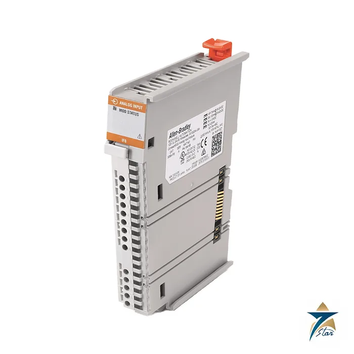
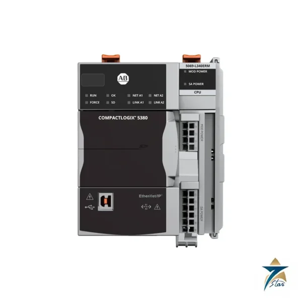
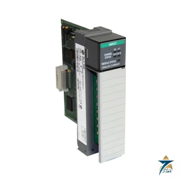
The Allen-Bradley 5069-IF8 is a Compact 5000 analog input module with eight channels. Each channel reads a voltage signal of ±10V, 0 to 10V or 0 to 5V, or a current signal of 0 to 20 mA or 4 to 20 mA, so a single module covers most 2-wire, 3-wire and 4-wire transmitters. The module sits next to a CompactLogix 5380 controller or a 5069-AENTR EtherNet/IP adapter and passes data to the controller as IEEE 32-bit floating point values.
The specification lists a sigma-delta converter with two 24-bit multiplexed ADCs, resolution up to 16 bits and a calibrated accuracy of 0.10 percent of full scale at 25 °C.
Technical specifications
| Parameter |
Specification |
| Catalog number |
5069-IF8 |
| Module type |
Compact 5000 analog 8-channel current/voltage input module |
| Inputs |
Series A: 8 differential; series B: 8 single-ended |
| Voltage ranges |
±10V, 0…10V, 0…5V |
| Current ranges |
0…20 mA, 4…20 mA |
| Resolution, voltage |
±10.5V: under 320 µV/count (15 bits plus sign); 0…10.5V: under 160 µV/count; 0…5.25V: under 80 µV/count (16 bits at 10 Hz notch filter) |
| Resolution, current |
0…21 mA: under 0.32 µA/count; 3.6…21 mA: under 0.27 µA/count (16 bits) |
| Calibrated accuracy at 25 °C |
0.10% of full scale (voltage and current) |
| Accuracy drift with temperature |
Voltage 0.20% and current 0.30% of full scale |
| Input impedance |
Voltage mode: more than 1 MΩ; current mode: 90 Ω typical (70…110 Ω) |
| Scan time |
625 µs per channel; 2.5 ms per group of channels 0…3 or 4…7 |
| Notch filter |
5, 10 (default 50/60), 15, 20, 50, 60, 100, 200, 500, 1000 Hz up to 62,500 Hz selectable |
| Conversion method |
Sigma-Delta, two 24-bit multiplexed ADC |
| Data format |
IEEE 32-bit floating point |
| Overvoltage / overcurrent protection |
±30V DC; current mode ±30 mA |
| Open-circuit detection time |
Less than 2 s |
| MOD power / SA power |
75 mA and 100 mA at 18…32V DC |
| Power dissipation, max |
Voltage mode 2.1 W; current mode 2.4 W |
| Isolation |
250V continuous, basic insulation; 50V functional isolation between SA power and inputs; no isolation between inputs |
| Noise rejection |
Common mode 130 dB at 50/60 Hz; normal mode 65 dB at 50/60 Hz |
| Slot width / dimensions |
1 slot; 144.6 x 22 x 105.4 mm (5.69 x 0.87 x 4.15 in.) |
| Weight, approx |
175 g (0.39 lb) |
| Mounting |
35 x 7.5 mm DIN rail (EN 50022), zinc-plated chromate-passivated steel |
| Module keying |
Electronic keying via programming software |
| Terminal block |
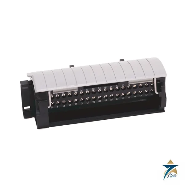
5069-RTB18-SPRING or 5069-RTB18-SCREW, ordered separately; screw RTB torque 0.4 N•m (3.5 lb•in) |
| Wire size |
0.34…1.5 mm² (22…16 AWG) shielded copper rated 105 °C; single wire per terminal; 3.5 mm max diameter including insulation (screw RTB) |
| Operating temperature |
0…+60 °C (+32…+140 °F) |
| Vibration / shock |
5 g at 10…500 Hz; 30 g operating shock |
| Temperature codes (as printed) |
North American T4; UKEX/ATEX T4; IECEx T4 |
| Certifications (as printed) |
cULus (UL files E322657, E334470), CE, UKCA, RCM, ATEX and IECEx Ex ec IIC T4 Gc, KC, CCC |
Channel configuration and diagnostics
Each channel is configured in the programming software, and the input type chosen in the module properties must match the device wired to the channel. The module offers selectable notch filters from 5 Hz to 62.5 kHz, an input digital filter and onboard data alarming, scaling to engineering units and real-time channel sampling. On overload it reports full scale with an overrange flag, and an open circuit is detected in less than 2 seconds.
The data sheet describes two hardware series: series A has eight differential inputs, while series B has eight single-ended inputs with terminals 0- to 7- connected internally. Check the series printed on the label when matching the wiring diagram to the module.
Power and wiring
Each module draws 75 mA of MOD power and 100 mA of SA power at 18 to 32V DC. Total passthrough current of MOD or SA power must not exceed 10 A. Use a 5069-RTB18 removable terminal block, which is ordered separately in screw or spring type. Compact 5000 RTBs accept one wire per terminal, and the module has two shield terminals.
Planning channels on the 5069-IF8
Group signals by type and by source before assigning channels. Because the inputs share a common reference on series B and there is no channel-to-channel isolation on either series, transmitters powered from different supplies, or signals referenced to different earth points, can interact through the module. Where a loop must be isolated from the rest, add a signal isolator in front of the channel rather than relying on the module.
- Count 2-wire, 3-wire and 4-wire transmitters separately, since each type is wired differently to the terminal block.
- Leave at least one spare channel per module for future instruments or for moving a faulty point.
- Choose the notch filter according to the fastest signal on the module; a slow level or temperature loop benefits from heavier filtering, while a fast pressure signal does not.
- Check the total passthrough MOD and SA current along the rail when this module joins an existing node.
Commissioning the module
Add the module to the controller project with the correct catalog number, series and electronic keying, then set the input type and range for every channel to match the instruments on the loop sheets. Configure scaling to engineering units in the module so that the controller logic reads values directly, and set alarm limits where the process requires them. Disable any unused channels so they do not raise open-circuit diagnostics.
Before connecting live instruments, verify each loop with a calibrator. Inject the lower and upper range values and a mid-point, and confirm the reading in the controller tag. Then reconnect the transmitter and compare the value with a local gauge or indicator. Keep a copy of the module configuration with the loop check records, which speeds up replacement if a module ever has to be changed.
Diagnostics and troubleshooting
- Open-circuit flag on a 4-20 mA loop: check the loop supply, the transmitter terminals and the removable terminal block seating.
- Overrange shown at full scale: confirm the configured range matches the signal and check for a wiring error such as a voltage source connected to a current input.
- Noisy readings: confirm the cable shield is terminated at one end on the module shield terminal and that signal cables are routed away from drive and motor cables.
- Module faulted: check MOD and SA power at the adapter or controller and the module keying in the project.
Oman and GCC panel considerations
Analog accuracy is more sensitive to heat than discrete I/O, as the temperature drift figures in the table show. In Oman, control panels in field shelters, pump stations and outdoor skids can reach high internal temperatures in summer, so plan cabinet cooling to keep the module well inside its operating range rather than close to the upper limit. Mount analog modules where airflow is best and away from heat-producing power supplies.
Dust and coastal humidity call for sealed enclosures with filtered or closed-loop cooling and tight cable glands. Salt-laden moisture on terminals can create leakage paths that show up as small offsets on current loops long before visible corrosion appears, so include a terminal inspection and a periodic calibration check in the maintenance plan for plants near the coast.
Documents and quotation
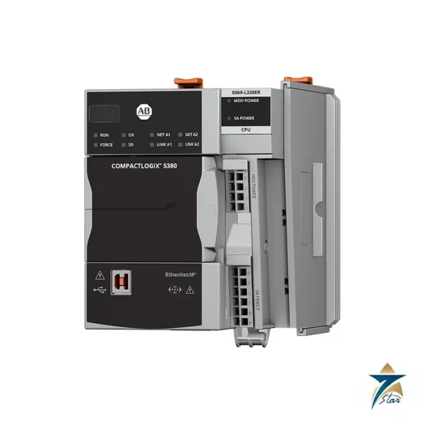
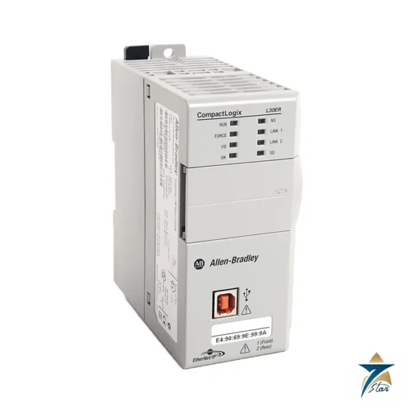
The Rockwell Automation Compact 5000 I/O specifications, publication 5069-TD001, are attached. See our PLC and I/O cards catalogue for CompactLogix controllers and related modules, and the 5069-L320ER controller. Confirm the exact catalog number, series letter and firmware or hardware revision on the product label, and the compatibility with your existing system, before ordering. Stock and lead time are confirmed at quotation.






Reviews
There are no reviews yet.