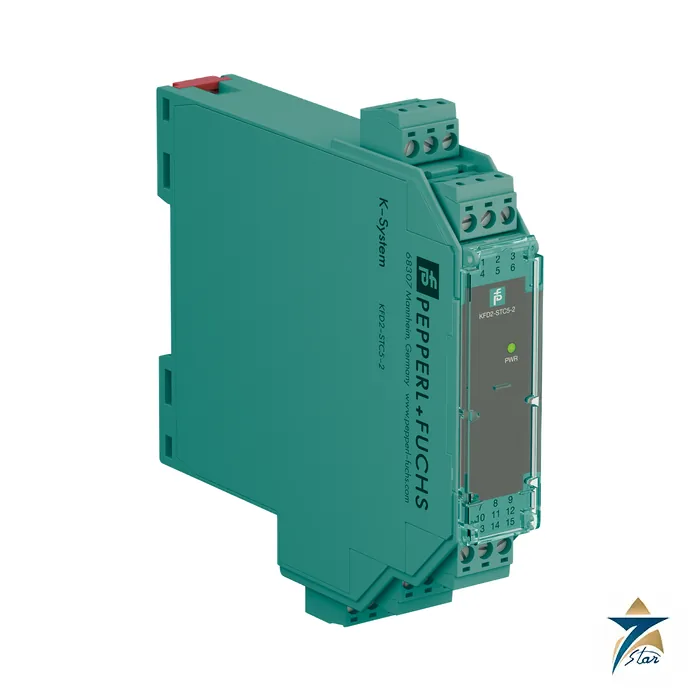
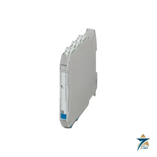
KFD2-STC5-2 two-channel SMART transmitter power supply
The KFD2-STC5-2 puts two complete SMART transmitter supply channels into a single 20 mm wide K-System housing. Each channel powers a 4-20 mA field transmitter, isolates it from the control system and hands on both the analog value and any superimposed HART communication. For a marshalling cabinet with many instruments, doubling the channel density per rail metre is the main reason to choose this module over the single-channel KFD2-STC5-1.
Seven Star LLC supplies the KFD2-STC5-2 in Oman and the GCC as an independent supplier in Muscat. This page explains the channel layout, the limits that govern loop design and the points to settle before ordering.
What the KFD2-STC5-2 designation tells you
The KFD2-STC5-2 follows the naming of its sibling KFD2-STC5-1, and the datasheet header identifies it as a 2-channel signal conditioner with a 24 V DC supply through the Power Rail, input for 2-wire and 3-wire SMART transmitters and 2-wire SMART current sources, and output 4 to 20 mA in sink or source mode.
Note that the two channels share a housing and a supply but not their signal circuits: the datasheet lists output-to-output isolation as functional insulation with a rated voltage of 50 V AC, while each input stays separated from its outputs and from the supply.
Technical specifications of the KFD2-STC5-2
| Parameter |
Specification |
| Manufacturer / part number |
Pepperl+Fuchs / KFD2-STC5-2 |
| Function |
SMART transmitter power supply, 2 channels, galvanic isolation |
| Supported SMART protocols |
HART, BRAIN, Foxboro |
| Field connections |
Channel I: terminals 1+, 2-, 3; channel II: terminals 4+, 5-, 6 |
| Input signal |
4 … 20 mA per channel |
| Available voltage to transmitter |
≥ 16 V at 20 mA; ≥ 20 V at 4 mA |
| Open circuit voltage / short-circuit current |
23 V / 25 mA |
| Output signal |
4 … 20 mA per channel, sink or source mode |
| Output load |
0 … 600 Ω; internal 250 Ω resistors at terminals 9 and 12 |
| External loop supply (sink mode) |
2 … 30 V DC |
| Supply |
18 … 30 V DC; power consumption ≤ 2.6 W at maximum load, dissipation ≤ 1.4 W |
| Accuracy |
Deviation ≤ 10 µA at 20 °C; drift ≤ 0.25 µA/K |
| Bandwidth |
Field to control side 0 … 7.5 kHz (-3 dB); reverse direction 0.3 … 7.5 kHz |
| Functional safety |
SIL 2 (IEC/EN 61508) |
| Ambient temperature |
-20 … 70 °C |
| Housing |
Type B2, 20 x 124 x 115 mm, approx. 150 g, 35 mm DIN rail, IP20 |
How the KFD2-STC5-2 handles two loops in one module
Each channel behaves like the single-channel module: it supplies the connected 2-wire or 3-wire transmitter, measures the loop current and reproduces it on an isolated output. Because the housing is shared, the supply current of both channels is drawn from the same 18 to 30 V DC source, and the datasheet quotes a combined power consumption of up to 2.6 W at full load. When the Power Rail supplies the module, no separate terminals need to be wired.
The output side offers the same sink or source choice per channel. Terminals 7 to 9 belong to channel I and terminals 10 to 12 to channel II, with an internal 250 Ω resistor at 9 and at 12 that can serve as the HART communication resistance. The load range is 0 to 600 Ω per output, a little narrower than the 800 Ω of the single-channel version, which matters for long output cable runs and for analog input cards with high input impedance.
HART communication is transferred in both directions and test sockets are present in the terminals. The deviation limit of 10 µA and the 0.25 µA/K temperature drift are identical to the single-channel module.
Placing the KFD2-STC5-2 next to its siblings
Choose the KFD2-STC5-2 when instruments are grouped in pairs, for example a duty and a standby transmitter at the same measuring point, or a pressure and a temperature transmitter on the same skid. For single points the KFD2-STC5-1 avoids wasting a channel, and for signal splitting to two receivers the KFD2-STC5-1.2O is the correct type.
Typical accessories are the KFD2-EB2 power feed module, the UPR-03 universal power rail and, if wiring combs are preferred, the K-DUCT profile rail mentioned in the K-System datasheets.
Selection and ordering checklist for the KFD2-STC5-2
- Count channels: two transmitters per module, and plan spare channels for expansion
- Confirm that both transmitters can work from at least 16 V at 20 mA
- Confirm the control-side input resistance against the 0 to 600 Ω load limit
- Decide sink or source per output
- Check the 2.6 W maximum power consumption against the cabinet heat budget
- Check that SIL 2 meets the safety-loop requirement
Installing and commissioning the KFD2-STC5-2
Mount the module on the DIN rail or Power Rail, wire the field side to terminals 1 to 6 and the control side to terminals 7 to 12. Label each channel clearly on the front, since both loops share one module and a mix-up during maintenance would swap two measurements.
During loop checks, test each channel independently with a loop calibrator or the transmitter simulation function and confirm the reading on the controller. The HART test sockets allow configuration of the transmitters without disturbing the other channel. Because a module failure affects two loops at once, a spare module on site is a sensible precaution for critical services.
Typical applications in Oman and the GCC
Dual-channel supply modules are common in compressor skids, wellhead control panels, boiler instrumentation and water treatment skids where transmitters occur in pairs. In Gulf plants, where cabinet space inside air-conditioned substations is limited and expensive, halving the rail length needed for analog inputs is a practical gain. The 70 °C ambient upper limit also leaves reasonable margin for cabinets in shaded outdoor shelters.
KFD2-STC5-2 compared with other STC5 variants
Values below come from the respective manufacturer datasheets.
| Part number |
Channels |
Output load |
Typical use |
| KFD2-STC5-1 |
1 |
0 … 800 Ω |
Single transmitter loop |
| KFD2-STC5-2 |
2 |
0 … 600 Ω per channel |
Paired transmitters |
| KFD2-STC5-1.2O |
1 in / 2 out |
0 … 600 Ω per output |
Signal split to two receivers |
Information to send with an RFQ for the KFD2-STC5-2
Please include the following in your enquiry.
- Number of transmitters and how many modules (two channels each) are needed
- Transmitter type and supply voltage requirement
- Supply arrangement: Power Rail or direct terminals
- Delivery date and spare module requirement
Documents and quotation
The manufacturer datasheet for the KFD2-STC5-2 is attached on this page, so the electrical data, terminal assignment and ambient limits quoted above can be checked against the original document before an order is placed.
Seven Star LLC supplies Pepperl+Fuchs products in Oman and the GCC as an independent supplier in Muscat. Send the quantity, the signal types and the project delivery date, and we will confirm availability and lead time in a written quotation.
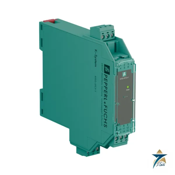
Other Models in the Pf Kfd2 Stc5 Range
Seven Star LLC supplies models from the Pf Kfd2 Stc5 range in Oman and the GCC. Compare the related models below and request a quote for the one that matches your application.




























Reviews
There are no reviews yet.