Calorimetric flow monitoring with no moving parts for water-based liquids
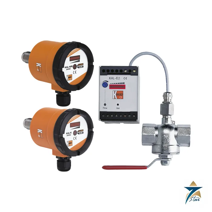
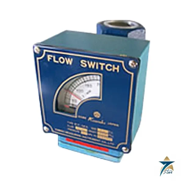
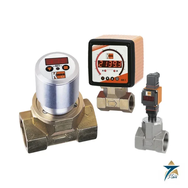
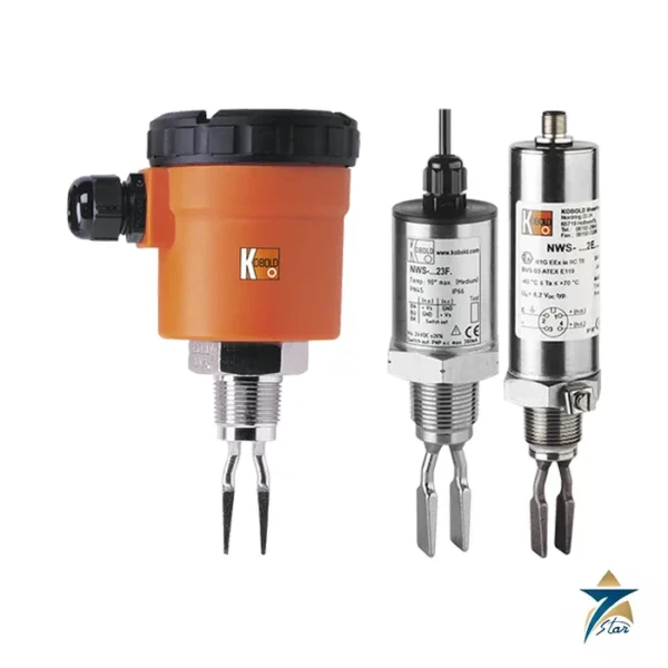
The KOBOLD KAL-K is an electronic flow monitor for water-based liquids. The end face of the sensor is heated a few degrees above the medium temperature; when the liquid flows, heat is carried away and the sensor cools, and that cooling is an accurate measure of flow velocity. A microcontroller compares the signal with stored reference data and gives an alarm signal, or a 4 to 20 mA signal proportional to flow velocity, when the actual flow deviates from the setpoint. The single-part sensor is less sensitive to soiling, and there are no moving parts and minimal pressure loss.
Temperature compensation is stored in an EEPROM that keeps its data for at least 10 years without power, so the switch point stays consistent as the medium temperature changes. The datasheet states the medium must be water-based with at least 90 % water content and is not suitable for oils and fuels.
Technical specifications
| Parameter |
Specification |
| Principle |
Calorimetric; switching or measuring range about 4 to 200 cm/s |
| Medium |
Water-based, at least 90 % water; not for oils and fuels |
| Temperature of medium |
-20 to +80 °C standard; 0 to +120 °C high-temperature version; CIP up to 140 °C non-operating |
| Maximum pressure |
100 bar (KAL-1132 and KAL-1140: 25 bar) |
| Warm-up / response time |
Up to 12 s / 5.6 to 12 s typically; 2 to 5.6 s on request (KAL-KS) |
| Sensor material |
Stainless steel 1.4301, 1.4305, 1.4571; Tri-Clamp version 1.4404 |
| Process connections |
G ¼, G ½, G ¾, M12 x 1, ¼” NPT, ½” NPT, ¾” NPT, Tri-Clamp DIN 32676 ½”; separate sensors also G ⅜, G 1, G 1¼, G 1½ |
| KAL-K compact supply |
24 VDC ±10 %, 110 VDC, 110 or 230 VAC; max. 4.5 W (typically 1.2 W) |
| KAL-K output |
Semiconductor PNP/NPN up to 400 mA (24 VDC) or relay (110 VDC 0.2 A, AC versions 5 A); N/O or N/C |
| KAL-A / KAL-AK |
4 to 20 mA output, ±10 % full scale, repeatability ±1 %; AK adds PNP/NPN alarm |
| KAL-E / KAL-EH electronics |
DIN-rail housing, changeover relay 250 V / 3 A; flow, flow trend LED chain, optional temperature monitoring |
| Sensor protection |
IP68 separate sensor, 2 m cable, up to 100 m line length; compact IP65 |
| Ex sensor approval |
ATEX II 1G Ex ia IIB T4 Ga; IECEx Ex ia IIB T4 Ga; electronics II (1)G [Ex ia Ga] IIB |
| Ambient temperature |
-20 to +60 °C compact; sensor -20 to +80 °C, high-temperature version 0 to +120 °C |
Model range
| Model |
Function |
| KAL-K |
Compact flow indicator with alarm contact |
| KAL-A |
Compact flowmeter with 4 to 20 mA output |
| KAL-AK |
Compact flowmeter and monitor, 4 to 20 mA plus alarm |
| KAL-E1 / E2 / E3 |
Separate electronics with relay; E2 adds trend display, E3 adds temperature monitoring |
The datasheet gives approximate measuring ranges in water by pipe size, for example DN 15 about 0.42 to 21.8 l/min, DN 25 about 1.18 to 59 l/min, DN 50 about 4.7 to 235 l/min and DN 100 about 18.8 to 942 l/min. Flow velocity approaches zero near the pipe wall, so deviations from these values depend on the nominal size, insertion depth and flow profile and can be considerable.
Ordering and installation
The KAL-K order example is KAL-K1215 S PG 3: material and connection, N/O or N/C contact, electrical connection (PG cable gland, M12 plug or circular connector) and supply code (3 = 24 VDC, 1 = 110 VAC, 0 = 230 VAC, 6 = 110 VDC). The switch point is set with a potentiometer and shown on an LED chain, with a red alarm and green flow-OK LED. Extended-length sensors are offered for ½” and ¾” connections.
Typical uses are dry-run and low-flow protection of pumps, cooling circuits and heat exchangers carrying water. Confirm before ordering: that the medium is at least 90 % water, the medium temperature against the version, the pressure, the pipe size and sensor insertion length, and the supply voltage.
Choosing the sensor position in the pipe
Because the KAL measures flow velocity at the sensor tip, its position in the pipe has more effect on the result than with many other flow switches. Place it in a straight run, away from bends, valves, pump discharges and reducers that disturb the flow profile, and set the insertion so the tip sits in the moving stream rather than close to the wall where velocity falls towards zero. Install it so the sensor stays fully covered by liquid; a horizontal pipe with the sensor entering from the side is usually better than from the top, where trapped air may collect.
On separate-sensor versions, plan the cable route between sensor and KAL-E electronics within the permitted line length, and keep it apart from power cables. In Ex areas, follow the ATEX or IECEx installation rules for intrinsically safe circuits listed in the approvals row.
Setting the switch point at commissioning
Allow for the warm-up time stated in the datasheet before judging the signal, since the sensor first needs to establish its temperature difference with the medium. Then run the circuit at normal flow and watch the LED chain, and reduce the flow to the level at which an alarm is wanted, for example the minimum cooling flow of a heat exchanger or the minimum flow below which a pump must stop. Adjust the potentiometer so the alarm changes state at that point, and confirm it switches back reliably when normal flow returns. Remember the typical response time when setting any delay in the pump or plant control logic.
For KAL-A and KAL-AK units, compare the 4 to 20 mA signal with the expected flow at a few operating points and treat it as an indication of trend rather than custody-grade measurement, given the stated tolerance.
Water quality and climate in Oman
Cooling water and process water in the Gulf can carry scale, sand or biological growth, particularly in open cooling towers that run hard through the summer. The single-part sensor is less sensitive to soiling, but deposits on the tip still change heat transfer and can shift the switch point over time. Where water treatment is poor, include sensor inspection in the cleaning schedule of the circuit. For compact versions outdoors, shade the housing from direct sun and keep within the ambient range, and make sure cable glands or M12 plugs are sealed against dust and humidity to preserve the IP65 rating.
Routine checks
At planned intervals, simulate a low-flow condition, for instance by throttling a valve, to prove that the alarm still operates and the pump or plant reacts as designed. Inspect and clean the sensor tip when the line is drained, and confirm that the medium is still water-based with at least 90 % water if additives such as glycol have been introduced to the circuit since commissioning.
Documents and quotation
The KOBOLD KAL-K datasheet (edition 1/08-2026) is attached to this page. Browse our Flow Indicators and Switches category for related instruments, or compare with the pFlow VC301R flow switch.
For a quotation, send the medium, pipe size and connection, sensor material, temperature and pressure, model (K, A, AK or E), supply voltage and any Ex requirement.





Reviews
There are no reviews yet.