A clamp-on power logger for energy surveys, demand and leakage checks
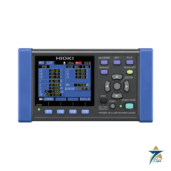
The Hioki PW3360-20 is a clamp-on power logger that measures single-phase to three-phase four-wire circuits and records the results on an SD card or in internal memory. It is meant for energy management work: load surveys, before-and-after comparisons of energy-saving measures, maximum demand checks, and finding the cause of unexplained consumption. The harmonic version, the PW3360-21, adds analysis of voltage and current harmonics up to the 40th order on 50/60 Hz lines.
The QUICK SET function guides the wiring step by step. The user selects the wiring type (for example 3P4W), the clamp and the destination, and the display then shows the colours of the leads to connect, checks the voltage and current connections and shows PASS or FAIL for each, with corrective action tips if a clamp is reversed or a phase is missing. This reduces the miswiring errors that otherwise make a logging run worthless.
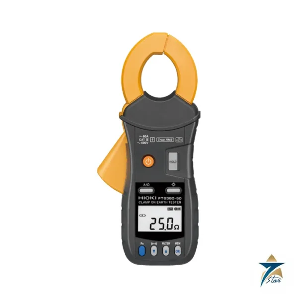
A demand graph shows 48 thirty-minute intervals and the maximum demand value and its time; a trend graph shows maximum, minimum and average values for any one selected item, calculated continuously at 200 ms intervals without gaps and saved per interval (1 s to 60 min). The instrument can also measure up to three separate single-phase two-wire circuits at once, count pulses from meters or production counters, and output pulses proportional to energy so that a data logger can record temperature and energy together. With optional leakage current clamp sensors it becomes a three-channel leakage current logger down to 50 mA.
Technical specifications
| Parameter |
Specification |
| Wiring types |
Single-phase 2-wire, single-phase 3-wire, three-phase 3-wire, three-phase 4-wire |
| Inputs |
Voltage 3 channels (U1 to U3); current 3 channels (I1 to I3) |
| Voltage |
600 V AC range; effective measurement range 90 V to 780 V; display range 5 V to 1000 V; peak +/-1400 V |
| Current sensors |
Clamp-on sensors 9694, 9695-02, 9660, 9695-03, 9661, 9669 (to 100 / 200 / 1 kA ranges), AC flexible sensors CT9667-01/-02/-03 (to 5 kA), leak sensors 9657-10 and 9675 (50 mA to 5 A) |
| Power range |
300.00 W to 9.0000 MW depending on voltage, current and line type |
| Measured items |
Voltage, current, frequency, active / reactive / apparent power, power factor, active and reactive energy, energy cost, demand values |
| Recording interval |
1 s to 60 min; up to one year at one-minute intervals on SD card |
| Pulse input / output |
Input 0 to 9999 counts per interval; output 1 Wh to 1000 kWh per pulse |
| Display |
3.5 inch TFT colour LCD, 320 x 240 pixels |
| Interfaces |
SD card, LAN (100BASE-TX, HTTP and FTP server), USB 2.0 |
| Maximum rated voltage to earth |
600 V CAT III / 300 V CAT IV (voltage input section) |
| Operating temperature |
-10 to 50 degC (0 to 40 degC on battery operation) |
| Power supply |
Optional battery set PW9002 gives about six hours of operation; optional voltage line power adapter PW9003 powers it from the measured lines |
| Dimensions |
Compact: about 180 x 100 x 48 mm (7.09 x 3.94 x 1.89 in) |
Software, options and model choice
Data from the SD card or internal memory can be loaded into Hioki’s Power Logger Viewer SF1001 for trend, summary and waveform display, harmonics, print and report printing. For live monitoring, the free Gennect One SF4000 PC software connects up to 30 instruments over LAN, shows monitor, graph and list views, controls the instrument remotely and downloads files automatically.
The sensor must be chosen to suit the conductor: small clamp sensors cover 5 A to 100 A or 500 A, the 9669 covers 100 A and 200 A and 1 kA ranges, and the CT9667 flexible sensors reach 5 kA on large cables and busbars. Magnetic adapter 9804 and voltage cords L9438-53 help when terminals are too shallow for alligator clips.
What to confirm before ordering
Specify the current sensors you need, since they are selected by current range from the brochure option list, and confirm what is included with the order code. List the circuit types and the highest current so the sensor ranges can be selected, and say whether leakage clamps, the battery set, the voltage-line power adapter, SD card, SF1001 or SF4000 software are required. If harmonic analysis is needed, ask for the PW3360-21. The attached brochure covers both models.
Planning a logging survey with the PW3360-20
A useful survey starts with a clear question. Decide whether the aim is to find the true maximum demand of a building, to compare consumption before and after a change, or to trace which feeder is driving a high bill. That question sets the recording interval, the length of the run and the circuits to log. A short interval over a few days captures motor starts and load swings; a longer interval over weeks shows weekly patterns and the effect of working hours and shifts.
- Walk the site first and note the wiring type, conductor sizes and the access to terminals for each measuring point.
- Choose sensors with a range that covers the expected peak current while still resolving the lower loads.
- Check that the SD card has space for the planned interval and duration before leaving the logger.
- Arrange how the instrument will be powered for the whole run, either from the measured lines through the adapter or from the mains, with the battery as backup.
Connecting and starting a recording
Work only on circuits where the team holds the right permits and wears suitable protective equipment, and observe the measurement category ratings of the instrument and leads. Connect the voltage leads first, then fit the clamps with the arrow pointing toward the load, and run QUICK SET to confirm every connection before recording. Set the clock correctly, because demand intervals and comparisons with utility bills depend on accurate time stamps.
Once the logger is running, secure the leads and clamps so they cannot be pulled off when a panel door is closed, and label the instrument with the start time and contact name. On the return visit, check the screen for any interruptions before stopping the recording, then copy the data to the PC for analysis.
Common problems and how to avoid them
- Negative power on one phase: a clamp is reversed or on the wrong phase; QUICK SET should catch this before recording starts.
- Gaps in the data: loss of power to the logger; review the power arrangement and battery condition.
- Values that do not match the bill: compare the time period and check that all incoming feeders were logged.
Energy surveys in Oman and GCC conditions
Air conditioning dominates electricity use in most Omani commercial and industrial buildings, so summer surveys show very different demand profiles from winter ones. Plan surveys to cover the hottest weeks when the aim is maximum demand, and repeat them in cooler months to measure the base load. The logger itself must stay within its operating temperature range, which matters in rooftop plant rooms and outdoor switchgear, and battery operation has a narrower range, so keep the instrument shaded and preferably inside the panel.
Dusty plant rooms and humid coastal substations call for basic care: keep the instrument in its carrying case between jobs, wipe clamp jaws clean so they close fully, and inspect lead insulation before every use.
Documents and quotation
For permanent panel monitoring see the Janitza UMG 96RM panel power analyser; for portable analysers, the portable test and measurement category. Send the model, sensors, accessories and quantity for a quotation from Seven Star LLC.











Reviews
There are no reviews yet.