Swagelok XS series excess flow valve for instrument and sample lines
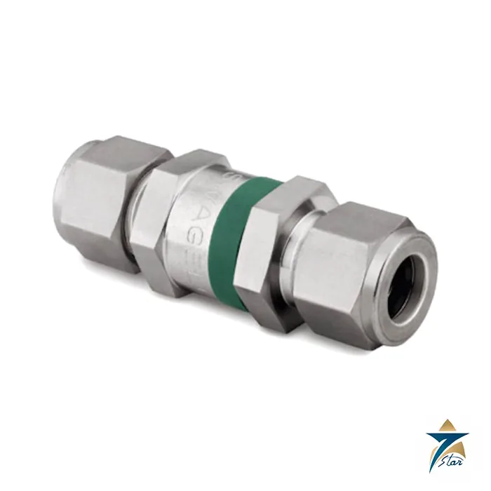
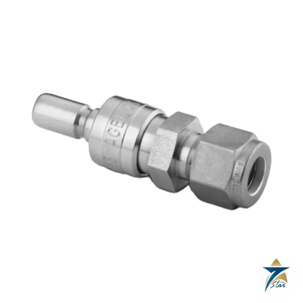
The Swagelok XS series is an in-line excess flow valve that closes automatically if the flow downstream rises far above normal, for instance when a tube, hose or fitting breaks. Fitted close to the source, it limits the uncontrolled release of gas or liquid from a cylinder, vessel or high-pressure line to a small bleed flow, and it resets by itself once the downstream pressure has equalized. The series uses a stainless-steel body and a slotted poppet, and it covers pressures up to 6,000 psig (413 bar). Seven Star LLC supplies Swagelok XS excess flow valves in Oman and the GCC as an independent supplier in Muscat.
The catalog calls the product line Industrial Excess Flow Valves and describes its purpose as stopping the uncontrolled release of system media if a downstream line ruptures. The XS series is available in three sizes, XS4, XS6 and XS8, matched to 1/4, 3/8 and 1/2 in. tube sizes, with threaded, welded-style and face-seal connections.
| Parameter |
Specification |
| Manufacturer / part number |
Swagelok XS series excess flow valve (ordering numbers such as SS-XSS4, SS-XSS6, SS-XSS8) |
| Working pressure |
Up to 6,000 psig (413 bar), subject to the end connection |
| Temperature |
Up to 400 °F (204 °C) with optional Kalrez O-rings; −10 to 400 °F range for the Kalrez option |
| Body, poppet and spring |
316 SS body and poppet (ASTM A479); 302 SS spring (A313) |
| Seals |
Fluorocarbon FKM O-ring with PTFE backup ring; PEEK backup ring optional |
| End connections |
1/8 to 1/2 in. and 6 to 12 mm: Swagelok tube fittings, NPT, ISO, SAE/MS, VCR and VCO |
| Series sizes |
XS4, XS6, XS8 |
| Water flow coefficient |
Cv 0.5 (XS4) and 1.1 (XS6) |
| Reset |
Automatic, through a bleed vent; spring returns the poppet |
| Flow through bleed vent |
Less than 1 % of the flow in the trip range (standard spring) |
How the XS excess flow valve works
In normal operation the spring holds the poppet in the open position and the process fluid flows past it through slots in the poppet. If an excess flow condition appears downstream, the pressure drop across the poppet rises quickly and the poppet moves against its spring to the tripped position, which shuts off the main flow. A small bleed vent passes a trickle of fluid so that, when the downstream pressure has built back up and equalized, the spring pushes the poppet back to the open position without any manual reset.
The slotted poppet is the key feature. It provides high flow capacity in the open position and avoids nuisance tripping at the normal operating flow. The catalog stresses the all-metal seat, which needs no maintenance, and notes that the spring-loaded actuation lets the valve work in any orientation.
- Automatic reset through the bleed vent, with no complicated bypass mechanism.
- Standard-spring bleed flow below 1 % of the trip-range flow; medium- and low-flow springs are available as options and may give a larger bleed flow.
- Each valve is factory tested for proper operation.
- Special cleaning to ASTM G93 Level C is processed for VCR and VCO end connections.
XS4, XS6 and XS8: sizes and ordering numbers
The three series sizes follow the end-connection size. The tube-fitting versions are the simplest to read: SS-XSS4 for 1/4 in. tube, SS-XSS6 for 3/8 in. and SS-XSS8 for 1/2 in., all rated 6,000 psig (413 bar) at 100 °F. Metric tube versions include SS-XSS6MM, SS-XSS8MM, SS-XSS10MM and SS-XSS12MM. Female NPT versions run from SS-XSF2 (1/8 in.) through SS-XSF4, SS-XSF6 and SS-XSF8, with pressure ratings falling from 6,000 psig to 5,300 psig at 3/8 in. and 4,900 psig at 1/2 in. Male NPT, mixed male NPT by tube and ISO, SAE and face-seal versions are also listed.
| Connection and series |
Ordering number |
Pressure rating at 100 °F |
Length A |
| 1/4 in. tube, XS4 |
SS-XSS4 |
6,000 psig (413 bar) |
2.43 in. (61.7 mm) |
| 3/8 in. tube, XS6 |
SS-XSS6 |
6,000 psig (413 bar) |
2.75 in. (69.9 mm) |
| 1/2 in. tube, XS8 |
SS-XSS8 |
6,000 psig (413 bar) |
2.97 in. (75.4 mm) |
| 1/4 in. male VCR |
SS-XSVCR4 |
6,000 psig (413 bar) |
2.28 in. (57.9 mm) |
| 1/2 in. male VCR |
SS-XSVCR8 |
4,300 psig (296 bar) |
2.73 in. (69.3 mm) |
| 1/2 in. male VCO |
SS-XSVCO8 |
6,000 psig (413 bar) |
2.36 in. (59.9 mm) |
The valve length depends on the end connection, and the dimensions in the catalog are for reference only.
Pressure-temperature ratings and O-ring options
The rating basis is ASME class 2500 with material group 2.2 and 316 SS. With the standard fluorocarbon O-ring the working pressure falls as the temperature rises, and the catalog lists 6,000 psig (413 bar) at −10 to 100 °F, then 5,160 psig at 200 °F, 4,910 psig at 250 °F, 4,660 psig at 300 °F and 4,280 psig at 400 °F, subject to the end connection and the O-ring limit.
| O-ring material |
Temperature rating |
| Fluorocarbon FKM (standard) |
Basis of the ratings above |
| Buna N (-BU) |
−40 to 250 °F (−40 to 121 °C) |
| Ethylene propylene (-EP) |
−50 to 300 °F (−45 to 148 °C) |
| Kalrez (-KZ) |
−10 to 400 °F (−23 to 204 °C) |
| Neoprene (-NE) |
−40 to 250 °F (−40 to 121 °C) |
A PEEK backup ring can be requested by adding -PK to the ordering number. Special cleaning and packaging is requested with -SC11.
Flow data and trip behavior
Excess flow valves must be sized on the trip flow, not on the maximum operating flow. The catalog provides air and water flow curves for XS4, XS6 and XS8, showing the open region, the trip range and the tripped condition against inlet pressure. For water, the trip range is 3.9 to 5.8 U.S. gal/min for the XS4 (Cv 0.5) and 8.2 to 10.0 U.S. gal/min for the XS6 (Cv 1.1). Springs with lower trip ranges are available, and the technical report MS-06-11 gives the detail.
To select a valve, find the normal operating flow at the installation pressure and make sure it sits clearly in the open region of the curve, then check that the flow expected after a rupture is well into the trip range.
Installation, commissioning and testing
Install the valve in the line with the flow direction arrow correct and as close as practical to the source of hazard. Swagelok tube fittings should be made up according to the Swagelok instructions, and the maximum working pressure of the tube and fittings must be checked against the valve rating, because tubing data can limit the system. After installation, pressurize slowly: a fast pressure rise downstream of the valve, for example when filling a long empty line, can trip it by creating a flow transient. The bleed vent then equalizes pressure and the valve resets.
- Do not use the valve as a shutoff valve; it is a protective device that trips on flow.
- Allow a slow fill of empty downstream lines to avoid nuisance trips.
- Do not swap non-Swagelok fittings into Swagelok tube fitting ends.
- Oxygen service needs special cleaning and the system designer’s own review.
Uses of excess flow valves in Oman and the GCC
Excess flow valves are commonly specified on compressed gas cylinder manifolds and bulk gas lines, on hydrogen and nitrogen supplies, on chemical injection and sampling lines at oil and gas facilities, and on analyzer shelter gas supplies in refineries and power stations. They are also used where a small-bore line from a pressurized vessel could release a toxic or flammable medium if damaged, which is relevant to lab, test and sampling installations in the region.
Because the valve is small and all-metal, it suits outdoor installations exposed to heat, dust and humidity, but it should be mounted so that rain and sand do not accumulate against the vent opening.
Selection checklist for an XS series excess flow valve
- Fluid and operating temperature.
- Maximum working pressure at the connection, against the end connection rating.
- Normal flow and the expected flow after a line break, to select the series size and spring.
- End connection type and size: tube, NPT, ISO, SAE, VCR or VCO.
- O-ring material and the need for PEEK backup rings.
- Cleaning level: standard SC-10 or special SC-11.
Information to send with an XS RFQ
- Medium, pressure, temperature and line size.
- Normal and trip flow requirements.
- Connection type and size, and any special cleaning or O-ring options.
- Quantity and delivery location.
Documents and quotation
The Swagelok Industrial Excess Flow Valves catalog for the XS series is attached to this page. Send your flow, pressure and connection data and we will confirm the ordering number and available documents.




















Reviews
There are no reviews yet.