The wiring base for FLEX I/O modules
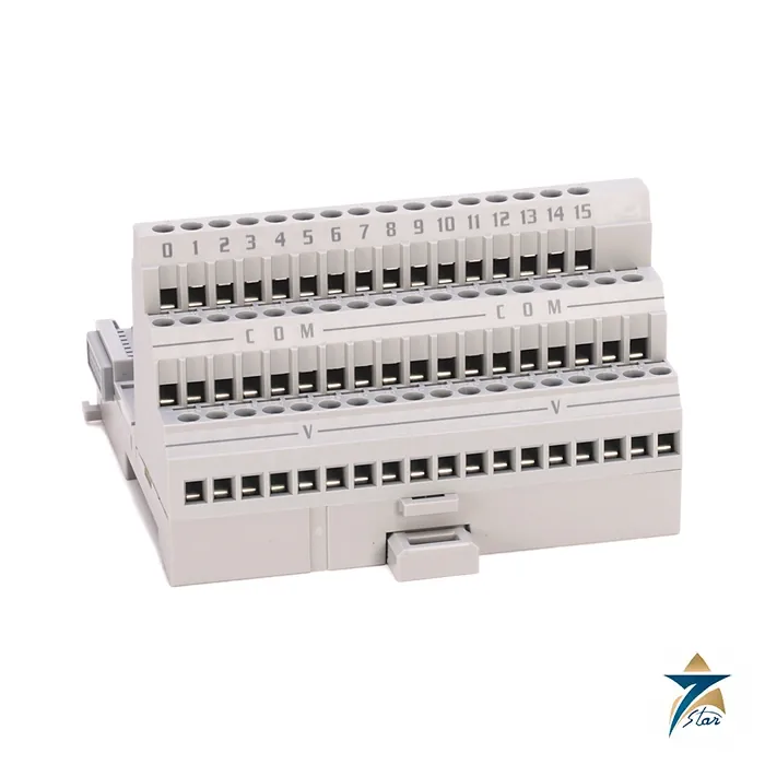
The Allen-Bradley 1794-TB3 is a cage-clamp terminal base for the FLEX I/O system. Every FLEX I/O module and adapter sits on a terminal base that carries the field wiring, the Flexbus backplane connection and the 24 V DC supply from one module to the next. The 1794-TB3 offers three terminal rows, with channel terminals 0 to 15, common terminals and supply in and out terminals, which suits 16-point digital and analog modules.
Because the module plugs into the base, a faulty module can be replaced without disturbing the field wiring, which shortens maintenance time on a distributed rack.
Technical specifications
| Parameter |
Specification |
| Catalog number |
1794-TB3 (1794-TB3K conformal coated) |
| Type |
FLEX I/O cage-clamp terminal base unit |
| Wire size |
0.34…3.3 mm² (22…12 AWG) solid or stranded copper wire rated at 105 °C (221 °F) or greater, 1.2 mm insulation maximum; strip length 5…6 mm (0.20…0.24 in.) |
| Terminal screw torque |
0.56…0.79 N•m (5…7 lb•in) |
| Conductors per terminal |
Do not wire more than 1 conductor on any single terminal |
| Flexbus |
5V DC, 640 mA |
| I/O terminals |
2 A maximum |
| V/COM terminals |
125V DC/AC, 50/60 Hz, 10 A |
| V/COM limit in UKEX/ATEX/IECEx |
60V AC or 75V DC maximum |
| Isolation voltage |
Capable of 125V continuous, basic insulation, field wiring terminals to Flexbus, or the lesser rating of the installed module; 2500V DC for 1 s test |
| Enclosure type rating |
None (open style) |
| Terminal layout |
Three terminal rows A, B and C with channel terminals 0…15, common terminals and 24V supply in/out terminals (e.g. +V at C-34 and C-51, common at B-16 and B-33) |
| Total base current |
Total current draw through any base must not exceed 10 A |
| Mounting |
35 mm DIN rail; the DIN rail grounds the base to chassis ground, use zinc-plated chromate-passivated steel rail |
| Temperature codes (as printed) |
North American T4A; UKEX/ATEX T4; IECEx T4 |
| Hazardous location |
Class I Division 2 Groups A,B,C,D approved; Zone 2 Ex ec IIC T4 Gc with special conditions (IP54 Zone 2 enclosure) as printed |
Wiring and electrical limits
The 1794-TB3 accepts solid or stranded copper wire from 22 to 12 AWG with insulation rated 105 °C or greater, stripped 5 to 6 mm, whereas the 1794-TB2 and the 1794-TB3T take the finer 24 to 16 AWG range. Do not terminate more than one conductor on a terminal and tighten the cage-clamp screws to 0.56 to 0.79 N•m. Terminals are rated 2 A for I/O, and the supply terminals carry up to 10 A at 125 V AC or DC, but the total current through a base must not exceed 10 A; the document also shows the wiring to follow when the total current is above or below 10 A.
Power daisy-chains from base to base through the supply in and supply out terminals, and the base grounds to the DIN rail. For Zone 2 installations the 1794-TB3 may not be used above 60 V AC or 75 V DC, and must be in an enclosure of at least IP54.
Which terminal base for which module
Each FLEX I/O module lists the bases it works with, and the keyswitch on the base is set to the number for that module. Use the 1794-TB3 for general modules, the 1794-TB3S for spring-clamp wiring, the 1794-TB3T for thermocouple modules, the 1794-TB2 where terminals 35 to 50 are not needed and the 1794-TBN for 250 V ratings. The 1794-TB3K is the conformal-coated version.
Selection checks for a FLEX I/O rack
Work through the rack module by module before ordering bases. For each position, read the installation instructions of the module that will sit on it and confirm that the 1794-TB3 appears in its list of compatible terminal bases; some modules need a different base from the family, and the wrong choice only becomes obvious on site. Count the field conductors for each channel, including commons and shields, and check that the three terminal rows give enough terminals without placing two wires on one terminal. Add up the supply current that will pass through the daisy-chained bases, because the per-base limit can be reached sooner than expected on a long rack with many outputs. Where the panel is in a classified area, confirm the hazardous-location conditions printed in the instructions before finalising the design.
Installation and commissioning
Mount the bases on the DIN rail in the order shown on the panel layout, and check that the Flexbus connection between neighbouring bases is made as the Rockwell installation instructions describe. Set the keyswitch on every base to the value for the module that will be fitted there before any module is installed, and mark the position on the drawing. Strip and terminate field wires to the length in the specification table, tighten each terminal to the stated torque, and give a gentle pull test to confirm the conductor is held. Label every wire with its channel reference so that loop checks can be done quickly.
During commissioning, check the supply voltage at the first base and at the far end of the chain, verify that each module is recognised by the adapter, and loop-check each channel from the field device through to the controller tag. Record any deviations from the drawings and correct the documentation before handover.
Maintenance
One of the practical advantages of a terminal base is that modules can be exchanged while the field wiring stays in place. Keep a record of keyswitch settings, recheck terminal tightness during planned shutdowns, and inspect the DIN rail grounding path whenever the rack is modified.
Panel conditions in Oman and the GCC
Remote I/O panels in Gulf plants are often installed near process equipment, sometimes outdoors in shaded kiosks, where heat, fine dust and coastal humidity are all present. Because the base is an open-style device, the enclosure provides all of the environmental protection; choose it with suitable sealing, cooling and a shaded position where possible. In corrosive or humid atmospheres, the conformal-coated 1794-TB3K listed above is worth discussing with the project engineer. Keep panel doors closed, maintain seals and clean dust from inside the panel during planned maintenance.
Documents and quotation
The Rockwell Automation FLEX I/O terminal base unit installation instructions are attached and cover the whole 1794-TB family. See our automation accessories and PLC and I/O cards pages for related products. Confirm the exact catalog number, series letter and firmware or hardware revision on the product label, and the compatibility with your existing system, before ordering. Stock and lead time are confirmed at quotation.











Reviews
There are no reviews yet.