- Automation & ControlView all 2,796 products
- Automation Accessories
- AC Drives
- PLC & I/O Cards
- Industrial Communications
- Vibration Monitoring
- Controllers & Data Acquisition
- Isolator & Barrier
- Safety Switches & Guard Locking
- Motor Soft Starters
- CCTV & Security
- Encoders
- Pneumatic Cylinders
- HMI Displays
- Servo Drives
- Industrial Computers
- Machine Vision
- Automation Software
- Robotics
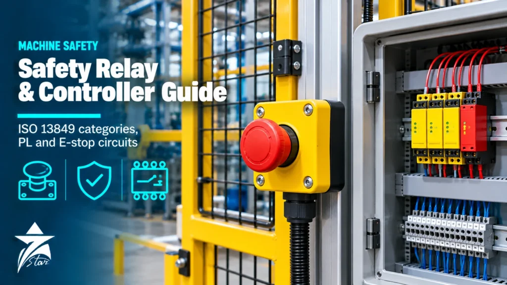
An emergency stop button wired to a normal control relay is not a safety function. If the relay contact welds, a wire shorts or a coil sticks, the machine may keep running when someone presses the button. A safety relay is designed so that such faults are detected and the machine is brought to a safe state. This guide explains how these devices work, how ISO 13849-1 categories and performance levels apply, how to wire common safety functions such as E-stop, guard doors and light curtains, and when a configurable safety controller is a better choice.
What a Safety Relay Does
A safety relay monitors one or more safety input devices and switches off the hazardous energy, usually by de-energising contactors or a drive safe torque off input. Compared with a standard relay it adds:
- Redundancy: two internal channels, each able to switch off the outputs on its own.
- Force-guided (mechanically linked) contacts to EN 61810-3, so a welded normally open contact keeps the linked normally closed contact open and the fault is detected.
- Self-monitoring: the relay checks its own channels at every switching cycle and will not restart after an internal fault.
- Cross-fault detection: on dual-channel inputs with pulsed or opposite-potential channels, a short between the two channels is detected.
- Feedback loop monitoring (EDM): normally closed mirror contacts of the external contactors are checked before every restart.
- Defined reset behaviour: manual monitored reset, manual reset or automatic start, selected to match the risk assessment.
ISO 13849-1: Categories and Performance Levels
ISO 13849-1 is the main standard for the safety-related parts of machine control systems. The risk assessment gives a required performance level (PLr) for each safety function, from PL a (lowest) to PL e (highest). The designed system must reach at least that level. The achieved PL depends on the architecture (category), the reliability of the components (MTTFd), the diagnostic coverage (DC) and measures against common cause failure (CCF).
| Category | Architecture | Behaviour on a single fault | Typical maximum PL |
|---|---|---|---|
| B | Single channel, basic principles | Safety function can be lost | PL b |
| 1 | Single channel, well-tried components | Safety function can be lost, but less likely | PL c |
| 2 | Single channel with periodic testing | Fault detected at the next test | PL d (with suitable MTTFd and DC) |
| 3 | Dual channel, redundant | Safety function maintained; most faults detected | PL d, PL e in some designs |
| 4 | Dual channel with high diagnostic coverage | Safety function maintained; faults detected in time, accumulation of faults considered | PL e |
IEC 62061 is an alternative standard that uses SIL levels instead of performance levels; PL d corresponds roughly to SIL 2 and PL e to SIL 3. Most manufacturer datasheets state both. For process plants, the related SIL concept is explained in our article on safety instrumented systems in Oman.
Stop Categories for Emergency Stop
IEC 60204-1 defines three stop categories, and the risk assessment decides which one each machine needs:
- Stop category 0: immediate removal of power to the actuators (uncontrolled stop). The relay opens its instantaneous outputs.
- Stop category 1: controlled stop with power available to bring the machine to a standstill, then power removed. A relay with time-delayed outputs gives the drive time to brake before its outputs open.
- Stop category 2: controlled stop with power left on the actuators, used only where a safe standstill is monitored; it is not permitted for emergency stop.
Typical Safety Circuits
| Safety function | Input device | Typical set-up |
|---|---|---|
| Emergency stop | E-stop push button or rope pull switch with two NC contacts | Dual-channel input, manual monitored reset, feedback loop of the contactors |
| Guard door monitoring | Interlock switch, coded non-contact switch or guard locking device | Dual-channel input, automatic or manual reset depending on whether the operator can walk behind the guard |
| Light curtain or laser scanner | Type 4 or Type 3 device with OSSD outputs | Relay input rated for OSSD signals; the sensor performs cross-fault detection itself |
| Two-hand control | Two-hand control station | Two-hand relay type IIIA, IIIB or IIIC to EN ISO 13851 with synchronous actuation monitoring |
| Safe stop of a drive | Any of the above | Safety output to the drive STO input, with time-delayed contacts for stop category 1 |
| Safety mats and edges | Pressure-sensitive mats or edges | Relay designed for the four-wire or resistive mat principle |
Selection of guard switches, coded actuators and guard locking is covered in detail in our safety interlock switch guide.
Wiring Practices That Keep the Performance Level
- Use two independent channels from the input device to the relay, and route them so a single cable crush cannot short both channels to a common potential when the relay cannot detect it.
- Wire the external contactors as two contactors in series, each driven by a separate safety output, with their mirror contacts in the feedback loop.
- Do not connect more E-stop buttons in series than the manufacturer allows for the required PL; fault masking in series-connected devices limits the achievable diagnostic coverage.
- Keep the reset button outside the danger zone with a clear view of it, and use a monitored reset that responds to the falling edge so a jammed button cannot cause a restart.
- Protect output contacts with the fuse rating given by the manufacturer, and use spark suppression on contactor coils to avoid contact wear.
- Document the safety function, its PLr, the circuit, and the validation test so the plant can repeat the proof test after modifications.
Safety Relay or Safety Controller?
A single safety relay handles one or two safety functions very well. When a machine has many E-stops, guard doors, light curtains and zones with different stop behaviour, wiring many relays together becomes complex and hard to modify. A configurable modular safety controller replaces them with software-configured logic and expandable I/O.
| Criterion | Safety relay | Modular safety controller |
|---|---|---|
| Number of safety functions | One or two | Many, with zones and muting |
| Configuration | Fixed by wiring and switches | Software, with simulation and reports |
| Diagnostics | LEDs on the unit | Detailed diagnostics and fieldbus status |
| Changes to the machine | Rewiring | Configuration change and revalidation |
| Cost for small machines | Lower | Higher |
| Network integration | Limited | Gateways for PROFINET, EtherNet/IP, Modbus TCP and others |
Controllers also handle functions that are hard to build with relays, such as muting of a light curtain while a pallet passes, safe speed monitoring with encoder modules, and zone-based stopping where one area of a line stops while the rest keeps running.
Where safety must run over the plant network itself, a safety PLC with a safety protocol such as PROFIsafe or CIP Safety is the next step up.
Selecting a Safety Relay: Checklist
- Required PL and category for each safety function from the risk assessment.
- Input type: dry contacts, OSSD outputs from electronic sensors, two-hand control or safety mats.
- Number of safety outputs (instantaneous and time-delayed) and auxiliary signalling outputs.
- Output rating, for example 6 A at 230 V AC, and whether external contactors are needed for the load.
- Supply voltage, typically 24 V DC or a wide-range AC/DC supply.
- Reset type, start-up test and whether a delay range for stop category 1 is needed.
- Housing width and terminal type, plus approvals such as TUV, UL and CE.
In hot Omani control panels, check the permitted ambient temperature of each relay and the derating of its output contacts, and keep panels ventilated or cooled where cabinets are exposed to the sun.
Safety Relays and Safety Components We Supply
Examples of relay modules, controllers and safety devices in our catalog. Each link goes to the product page.
Browse more in our safety switches and guard locking category. To get a quotation, send the safety function, required PL or SIL, input devices, number of outputs, supply voltage and reset type, or the part number of the existing unit, through our quote request form or to [email protected].
Sourcing Machine Safety Components in Oman Through Seven Star LLC
Seven Star LLC is an independent supplier in Oman of emergency stop and guard monitoring relays, modular safety controllers, emergency stop devices, interlock switches and light curtains for machinery, packaging, conveyors and process skids. We quote products from manufacturers such as Pilz, SICK, Phoenix Contact, Allen-Bradley, EUCHNER and Banner Engineering, and can match an existing unit by part number for replacement. Ratings, approvals and lead time are confirmed against the manufacturer data at quotation.
Frequently asked questions
What is the difference between a safety relay and a normal relay?
A safety relay has redundant channels, force-guided contacts and self-monitoring, so a welded contact, short circuit or internal fault is detected and the machine cannot restart. A normal relay has none of these features and cannot be used on its own for a safety function.
Which performance level do I need for an emergency stop?
The required performance level comes from the risk assessment of the specific machine. Many machine E-stop functions are specified at PL c to PL d, and some high-risk machines need PL e. The relay, input devices and contactors together must reach the required level.
Can I connect several E-stop buttons to one relay unit?
Yes, E-stop buttons are often wired in series, but fault masking limits the diagnostic coverage. Check the manufacturer guidance and ISO/TR 24119 for the maximum number of devices in series for the required performance level.
What is a monitored manual reset?
A monitored manual reset only restarts the outputs when the reset button is pressed and released, so a stuck or bridged button cannot cause an automatic restart. It is commonly required for E-stop circuits and walk-in guards.
When should I use a safety controller instead of safety relays?
Use a modular safety controller when a machine has many safety functions, several zones, muting or frequent changes. It reduces wiring, gives better diagnostics and can be connected to the plant network through gateways.
Who supplies safety relays in Oman?
Seven Star LLC is an independent supplier in Oman that quotes safety relays, safety controllers, E-stop devices and safety light curtains from leading manufacturers. Send your requirements through the quote request form or to [email protected].
Was this guide helpful?One click helps us write better guides for engineers.
Thank you! Glad it helped. Need this equipment for your project? Request a quotation
Thank you. We will use this to improve the guide.