- Automation & ControlView all 1,754 products
- AC Drives
- Industrial Communications
- PLC & I/O Cards
- Vibration Monitoring
- Automation Accessories
- Controllers & Data Acquisition
- CCTV & Security
- Safety Switches & Guard Locking
- Isolator & Barrier
- Encoders
- Industrial Computers
- Servo Drives
- Motor Soft Starters
- HMI Displays
- Pneumatic Cylinders
- Automation Software
- Machine Vision
- Robotics
















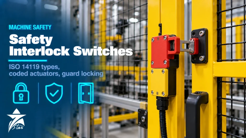
A safety interlock switch is the component that stops a machine when a guard opens, and it is also the safety component most often bypassed, mis-wired or chosen without reference to the standard. Choosing one is not just a matter of picking a switch that fits the door: the device type, actuator coding, locking principle, wiring architecture and the Performance Level required by the risk assessment all have to line up. This guide explains the ISO 14119 interlocking device types, coding levels, when guard locking is required, how to prevent defeat, how series wiring affects diagnostics and how the switch fits into an ISO 13849-1 safety function.
The Standards That Apply
Three standards cover most interlocking decisions for machinery:
- ISO 14119 (interlocking devices associated with guards): design and selection principles. The 2024 edition replaced the 2013 edition, added trapped key systems as a fifth device type and brought the fault-masking criteria from ISO/TR 24119 into an annex.
- ISO 13849-1 (safety-related parts of control systems): defines the Performance Level (PL a to e) and the categories (B, 1, 2, 3, 4) used to design and verify the complete safety function. IEC 62061, using SIL, is the alternative route.
- ISO 13855 (positioning of safeguards): calculates the minimum distance between a guard opening and the hazard based on approach speed and stopping time, which determines whether guard locking is needed.
Fixed and movable guard design itself is covered by ISO 14120, and switches with direct (positive) opening contacts are defined in IEC 60947-5-1.
ISO 14119 Interlocking Device Types
| Type | Actuation principle | Typical examples | Notes |
|---|---|---|---|
| — | — | — | — |
| Type 1 | Uncoded, mechanical | Hinge switches, cam-operated position switches, roller plungers | Simple and robust; easier to defeat; use positive-mode actuation |
| Type 2 | Coded, mechanical | Tongue (separate actuator) switches | Common on doors; actuator shape is the code, usually low coding |
| Type 3 | Uncoded, non-contact | Uncoded inductive or magnetic sensors | Easy to defeat with any metal or magnet; use with care |
| Type 4 | Coded, non-contact | RFID safety switches, coded magnetic sensors | Tolerant of misalignment, hygienic designs, low to high coding |
| Type 5 | Trapped key | Key transfer and key exchange systems | Added in ISO 14119:2024; key coding prevents duplicate keys |
Positive-mode actuation
For mechanically actuated switches, ISO 14119 relies on positive-mode actuation: the guard movement forces the switch contacts open through a rigid mechanical link, so a welded contact or broken spring cannot keep the circuit closed. Switches with direct opening action are marked with the symbol of an arrow in a circle, according to IEC 60947-5-1 Annex K. A cam that pushes the plunger when the guard opens is positive mode; a switch that relies on a spring to open its contacts when the guard moves away is not.
Coding Levels and Defeat Prevention
ISO 14119 assigns coding levels to coded actuators:
- Low: 1 to 9 code variants. Most tongue-actuator switches, where any actuator of that model fits any switch.
- Medium: 10 to 1,000 variants.
- High: more than 1,000 variants. Typically RFID switches that accept only one paired actuator, sometimes with a limited number of re-teach operations.
Defeat is a real problem on production machines: operators bypass guards to clear jams or save cycle time. The standard requires the designer to consider the motivation to defeat and to apply measures in proportion to it. Typical measures include:
- Mounting the switch and actuator out of reach or behind the guard where they are not accessible when the guard is open.
- Using permanent fixings such as one-way screws, rivets or welding for the switch and actuator.
- Concealing the switch or shrouding the actuator so a loose actuator cannot be inserted.
- Selecting medium or high coded devices when low-coded devices could be defeated with a spare actuator.
- Plausibility monitoring in the control system, for example checking that the guard opened during a cycle that required access.
The best measure is often to remove the reason to defeat: make the guarded task easy to do safely, with suitable operating modes and access for routine adjustments.
When Guard Locking Is Required
A standard interlock stops the machine when the guard opens. That is enough only if the hazard has stopped before a person can reach it. If a spindle, saw blade, flywheel or centrifuge keeps running after the stop command, or if the opening is close to the hazard, the guard must remain locked until the hazard is gone. Compare two times:
- Stopping (run-down) time: measured from guard opening to full stop or safe state, at worst case.
- Access time: how long a person needs to open the guard and reach the hazard, derived from the distance and the approach speed in ISO 13855.
If stopping time exceeds access time, use guard locking released by a standstill monitor or a safe time delay. Guard locking is also used for process protection, for example keeping a door shut during a cycle so the product is not spoiled, but in that case the locking function may not be safety-relevant.
Locking principles
- Spring-applied, power-to-unlock (mechanical locking): a spring holds the bolt locked; energising the solenoid releases it. On power failure the guard stays locked, which is the normal choice for personnel protection. Provide a means of release for maintenance and rescue.
- Power-to-lock, spring-to-unlock (electrical locking): the solenoid must be energised to keep the guard locked. A power failure unlocks the guard immediately, so this principle is usually limited to process protection or to cases where the risk assessment shows that sudden release is safe.
- Bistable locking: some electronic guard locks hold their last position without continuous power, combining low energy consumption with defined behaviour on power loss; check how the manufacturer defines the safe state.
Guard locks are rated for a holding force (FZh). Make sure the guard, hinges and fixing points can withstand the forces a person can apply, otherwise the guard will deform before the lock fails.
Release functions
ISO 14119 distinguishes several manual release functions. An auxiliary release is operated with a tool or key from outside, typically for maintenance after a power failure. An emergency release can be operated without tools from outside the hazard zone. An escape release is operated from inside the danger zone so a person who is trapped can open the guard. Where a person can enter a cell bodily and the door can close behind them, an escape release is essential.
Wiring Architectures and Series Connection
The switch is only the input subsystem. The complete safety function includes the evaluation unit (safety relay or safety PLC) and the output subsystem (contactors, safe torque off on a drive, safety valves). Typical arrangements:
- Single-channel, single switch: suitable for low PL requirements only.
- Dual-channel with one switch: two contacts in one device. The mechanical actuator is a single point of failure, so the achievable PL depends on whether a fault exclusion on the mechanical parts is justified; this is generally accepted only up to PL d.
- Two independent switches: often one Type 2 and one Type 1, or two non-contact switches, giving diversity and redundancy for PL d or PL e.
- Coded electronic switches with OSSD outputs: dual-channel semiconductor outputs with internal diagnostics and cross-fault detection, rated by the manufacturer with a PFHd value and suitable for PL e when correctly connected.
Fault masking in series wiring
Many machines connect the potential-free contacts of several door switches in series to one safety relay. If two guards are opened at the same time, a fault in one switch can be reset or hidden by the other, so the evaluation unit cannot detect it. This fault masking reduces the diagnostic coverage you can claim, and with it the achievable PL. ISO 14119:2024 Annex J, which incorporates the former ISO/TR 24119, gives criteria based on the number of guards, how often they are opened and how many people use them. Electronic switches designed for series connection, each with its own diagnostics, avoid this limitation. For process-plant safety systems the same discipline of architecture and diagnostics applies; see our article on safety instrumented systems and safety PLCs.
Performance Level Basics
ISO 13849-1 asks for the required Performance Level (PLr) from the risk graph: severity of injury, frequency and duration of exposure, and possibility of avoiding the hazard. The achieved PL of the designed function must meet or exceed PLr, and it depends on:
- Category: the structure (single channel, single channel with testing, or redundant channels with fault detection).
- MTTFd: mean time to dangerous failure, calculated for electromechanical switches from the manufacturer’s B10D value and the number of operations per year.
- DCavg: diagnostic coverage achieved by monitoring, reduced by fault masking.
- CCF: measures against common-cause failure, such as diversity, separation and protection against overvoltage.
Electromechanical switches wear: a door opened every few minutes on three shifts accumulates operations quickly, and the B10D value may then limit the PL or require a replacement interval. Non-contact coded switches have no mechanical wear in the switching element and are rated directly with a PFHd figure.
Selecting a Safety Interlock Switch for the Guard
- Guard type: hinged doors suit hinge switches or tongue switches near the closing edge; sliding doors suit tongue, RFID or locking devices at the closing end.
- Alignment and sag: heavy doors drop over time; non-contact switches tolerate more misalignment than tongue actuators.
- Environment: IP67 or IP69K for washdown, stainless steel housings for food and chemical areas, and Ex-rated versions where the machine sits in a classified area.
- Diagnostics and connection: OSSD outputs, status outputs to the PLC, M12 connectors to simplify series wiring.
- Guard locking need: run-down time, process protection, locking principle and release functions.
- Lifecycle: mechanical life in operations, B10D and replacement intervals.
Installation and Common Mistakes
- Using the switch or actuator as a door stop; the guard must have its own mechanical stop so the switch only senses position.
- Mounting with standard screws that make removal trivial when the risk assessment calls for permanent fixing.
- Spare actuators left on the machine or in the toolbox, which invites defeat with low-coded switches.
- Series wiring many low-diagnostic switches without checking fault masking.
- Using power-to-lock guard locks on machines with long run-down times.
- Forgetting an escape release on walk-in cells.
- Not validating: the safety function must be tested after installation and after any modification.
Maintenance and Testing
Check every interlock at a defined interval: open each guard and confirm the machine stops or cannot start, check that guard locking holds against a firm pull, inspect actuators and housings for damage, loose fixings and signs of tampering, and confirm that any replacement switch has the same type, coding and contact arrangement as the original. Record the results. Where the safety function relies on periodic testing (for example Category 2 structures), the test interval is part of the design and must be followed.
Operating in GCC Conditions
Machines in Oman and the GCC often run in hot, dusty workshops or outdoors under shade structures. Check the maximum operating temperature for solenoid guard locks, which generate heat of their own; fine dust can enter tongue-actuator slots and jam the mechanism, so choose designs with sealed entries or non-contact switches; and in food, water and desalination plants, specify stainless steel and high IP ratings for washdown and chlorinated environments.
Safety Switch Selection Checklist
- Required Performance Level (PLr) from the risk assessment
- Guard type, size, hinge or sliding, and expected misalignment
- ISO 14119 type and coding level required for defeat prevention
- Stopping time versus access time: interlock only, or guard locking
- Locking principle and holding force, plus auxiliary, emergency and escape release
- Contact arrangement or OSSD outputs, and status signals
- Series connection plan and fault-masking assessment
- Evaluation unit: safety relay or safety PLC inputs
- B10D or PFHd data, operations per year, replacement interval
- IP rating, temperature range, material and Ex rating if needed
Safety Interlocks and Relays We Supply
These examples cover the interlock types and the safety relays that evaluate them.
| Product | Type | Where it fits |
|---|---|---|
| Schmersal AZM201 Solenoid Interlock Safety Switch | Solenoid interlock safety switch | Guards that must stay locked until the machine has stopped. |
| EUCHNER CTP-L1-BP-U-HA-AZ-SA Guard Locking Safety Switch | Guard locking safety switch | Machine guards with transponder coding. |
| EUCHNER CES-IA-BR-U-C07-SA Non-Contact Safety Switch Set | Non-contact safety switch | Guards where hygiene or misalignment rules out a mechanical switch. |
| Banner SI-LS42 Locking Safety Interlock Switch | Locking safety interlock switch | Guard doors on machinery. |
| Pilz PNOZ s3 Compact Safety Relay for E-STOP and Safety Gates | Safety relay | Emergency stop and safety gate monitoring. |
| Banner EZ-SCREEN LS Type 4 Safety Light Curtain | Type 4 safety light curtain | Openings that need frequent access without a physical guard. |
Send the guard type, required performance level and the machine control system through our quote request form.
Sourcing Safety Interlock Switches Through Seven Star LLC
Seven Star LLC supplies safety switches and guard locking devices on request, together with safety relays, safety PLC I/O from our PLC and I/O card range and other automation and control components, from manufacturers such as Pilz, Schmersal, Euchner and SICK. We help with selection and cross-checking part numbers, and availability and lead time are confirmed at quotation.
Replacing an interlock or specifying a new guard? Send us the switch label or model code, actuator type, locking requirement and required PL, and we will return a matched quotation.
Frequently asked questions
What are the interlocking device types in ISO 14119?
ISO 14119 classifies interlocking devices by actuation principle and actuator. Type 1 is uncoded mechanical (for example a hinge or cam-operated switch), Type 2 is coded mechanical (a shaped tongue actuator), Type 3 is uncoded non-contact, Type 4 is coded non-contact (for example RFID or coded magnetic) and, since the 2024 edition, trapped key systems are Type 5.
What do low, medium and high coding levels mean?
The coding level describes how many different actuator codes exist. Low coding means 1 to 9 variants, medium 10 to 1,000 and high more than 1,000. A high-coded switch accepts only the actuator taught or paired to it, which makes defeating it with a spare actuator much harder.
When is guard locking required instead of a simple interlock?
Guard locking is needed when the hazardous motion takes longer to stop than a person needs to open the guard and reach the hazard. Compare the machine's stopping or run-down time with the access time derived from the safety distance; if the hazard is still present when the hand arrives, the guard must stay locked until a standstill monitor or safe time delay releases it.
What is the difference between spring-applied and power-to-lock guard locking?
A spring-applied (power-to-unlock) guard lock stays locked when power is lost and needs energy to release, which is the normal choice for personnel protection. A power-to-lock device unlocks when power fails, so it is generally limited to process protection or applications where the risk assessment shows that sudden release on power loss is safe.
Can several safety switches be wired in series?
Yes, but with potential-free contacts in series a fault in one switch can be masked when other guards are opened and closed, which reduces the diagnostic coverage you can claim. ISO 14119:2024 Annex J (formerly ISO/TR 24119) gives criteria for this. Electronic switches with OSSD outputs and internal diagnostics are designed for series connection while maintaining high Performance Levels.
What Performance Level can a safety interlock switch achieve?
The switch is only one part of the safety function, which also includes the logic unit and output devices such as contactors. A dual-channel architecture with suitable switches, a safety relay or safety PLC, and monitored contactors can reach PL d or PL e depending on component data and diagnostics. The manufacturer's B10D or PFHd values are used in the ISO 13849-1 calculation.
Was this guide helpful?One click helps us write better guides for engineers.
Thank you! Glad it helped. Need this equipment for your project? Request a quotation
Thank you. We will use this to improve the guide.