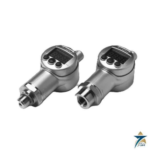
Four switching points and a large display in one panel-style housing
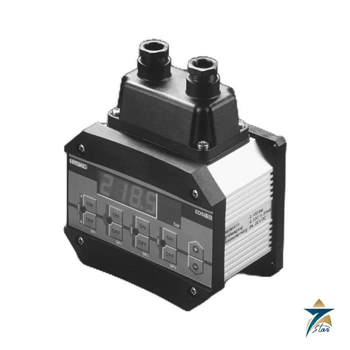
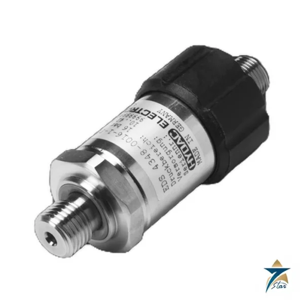
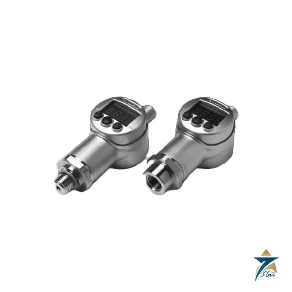
The Hydac EDS 1791-N-100-000 (HYDAC part number 906204) is a microprocessor pressure switch with a four-digit, 13 mm red LED display and four relay outputs. Each of the four switching points and switch-back points is set independently from the keypad. An analogue output, 4 to 20 mA or 0 to 10 V, allows the same device to feed a PLC. The HYDAC datasheet names hydraulics and pneumatics as the main fields of use.
Compared with the compact EDS 3000 and 8000 switches this model is bigger, about 800 g in an anodised aluminium housing, and is connected through a 14-pole terminal block. It suits control panels, test stands and power units that need several set points on one pressure.
Technical specifications
| Parameter |
Specification |
| HYDAC part number |
906204 |
| Model code |
EDS 1791-N-100-000 |
| Measuring range |
0 to 100 bar (1450 psi) |
| Overload pressure |
200 bar (2900 psi) |
| Burst pressure |
500 bar (7250 psi) |
| Mechanical connection |
G1/4 DIN 3852 threaded port; 20 N·m |
| Wetted parts |
Stainless steel |
| Switching outputs |
4 relays with changeover contacts, two groups with common supply |
| Switching rating |
0.1 to 250 V AC/DC; 0.01 to 2 A; 50 W / 400 VA |
| Relay cycles |
20 million at minimum load; 1 million at maximum load |
| Setting range of switching points |
1.5 % to 100 % FS (switch-back 1 % to 99 % FS) |
| Analogue output |
4 to 20 mA or 0 to 10 V, selectable |
| Accuracy class |
N = 1 %; repeatability 0.5 % FS max. |
| Reaction time |
Approx. 20 ms |
| Display |
4-digit LED, 13 mm digits |
| Supply voltage |
22 to 32 V DC |
| Current consumption |
Approx. 200 mA |
| Electrical connection |
14-pole terminal block |
| Housing |
Anodised aluminium; approx. 800 g |
| Operating temperature |
-13 to +158 °F |
| Fluid temperature |
-13 to +176 °F |
| Protection class |
IP 65 |
| Vibration / shock |
5 g / 10 g |
| Approvals as printed |
CE (EN 61000-6-1/2/3/4) |
Order code
The datasheet code is EDS 1 7 9 X – X – XXX – 000. The 9 selects the G1/4 DIN 3852 port, the display digit 1 shows bar (2 would show psi), the letter N gives 1 % accuracy (P gives 0.5 %), 100 is the range in bar and 000 the standard modification. Ranges of 16, 40, 100, 250, 400 and 600 bar are listed, so confirm the range against your highest system pressure before ordering.
Functions and settings
The microprocessor provides switch-on delays for relays 1 to 4 from 0.00 to 90 seconds, which keeps fast pressure peaks from triggering the relays. The direction of each relay (N/C or N/O) can be set and all settings are made on the keypad. The same device can therefore serve as a four-stage pressure monitor, for example for low-pressure alarm, pump start, pump stop and high-pressure shutdown on a hydraulic power unit.
Wire the relay groups with the common supply of each group in mind, since two groups share a supply, and fit a fuse or contact protection where inductive loads are switched. The housing is IP 65, so route cables with proper glands.
With four switching outputs a single unit can monitor several pressure thresholds, for example a low alarm, a pump-on level, a pump-off level and a high alarm. Plan the relay wiring and load ratings for each output and keep the supply within the range listed in the datasheet.
Selection considerations for a multi-point pressure switch
The most important choice is the measuring range. A range that is too large wastes resolution and makes small set points harder to adjust; a range that is too small leaves the sensor exposed to pressure spikes near its overload limit. A sensible rule is to pick the range so that normal working pressure sits well inside the scale, while the highest expected peak, including pump start-up and valve closure surges, stays below the overload figure in the table. The accuracy class should be matched to the job: alarms and pump control usually work well with the standard class, while test stands may justify the higher accuracy option listed in the order code.
The electrical side deserves equal attention. Each relay has a defined switching rating, so heavy loads such as motor contactors with large coils, solenoid valves or lamps should be checked against it, and an interposing relay used where the load is higher. The supply must be a stable DC source within the stated range, sized for the current consumption of the unit.
Integration in hydraulic power units and test benches
On a hydraulic power unit the four relays can take over functions that would otherwise need several mechanical switches, while the analogue output sends the live pressure value to the PLC or a recorder. This combination gives both local protection that works without the controller and remote visibility for trending. On test stands, the large display lets the operator read pressure directly at the bench.
Installation and commissioning practice
The threaded port should be fitted with a suitable seal and tightened to the torque given in the specifications. Mounting the unit on a short, rigid branch away from strong vibration sources helps keep readings stable and protects the electronics, even though shock and vibration limits are stated. Where the hydraulic system produces sharp pressure peaks, a snubber or damping element on the gauge line can reduce stress on the sensor and avoid nuisance switching, and the adjustable switch-on delays can be used for the same purpose.
At commissioning, each switching point and switch-back point should be entered, the relay direction chosen to suit fail-safe logic, and the behaviour checked against a reference gauge. Alarm outputs are often configured so that loss of supply leads to the safe state. Recording the final settings in the machine documentation makes later replacement straightforward.
Operating in Gulf conditions
Hydraulic equipment in Oman and the GCC frequently runs in hot workshops, on mobile plant or outdoors, with fine dust and high humidity near the coast. The operating and fluid temperature limits should be compared with the actual conditions at the mounting point, which may include radiant heat from the power unit itself. Proper cable glands keep the IP 65 rating effective against dust and moisture, and the display should be shielded from direct sunlight so that it remains readable. Periodic checks of set points, terminal tightness and the condition of the threaded seal help keep the switch reliable through hot seasons.
Documents and quotation
The datasheet is attached. Please include the code and your relay requirements. See also our pressure instrumentation range.







Reviews
There are no reviews yet.