Type 2 surge protection for TN-S distribution boards
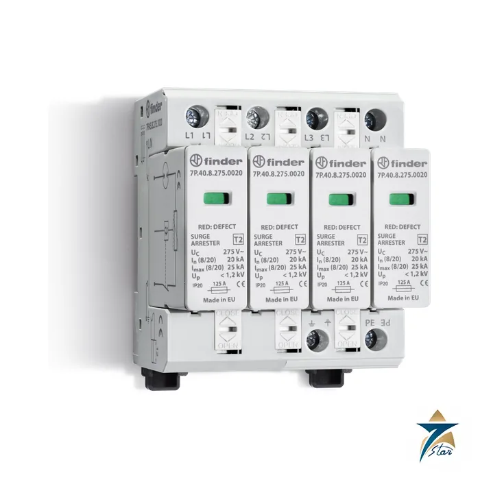
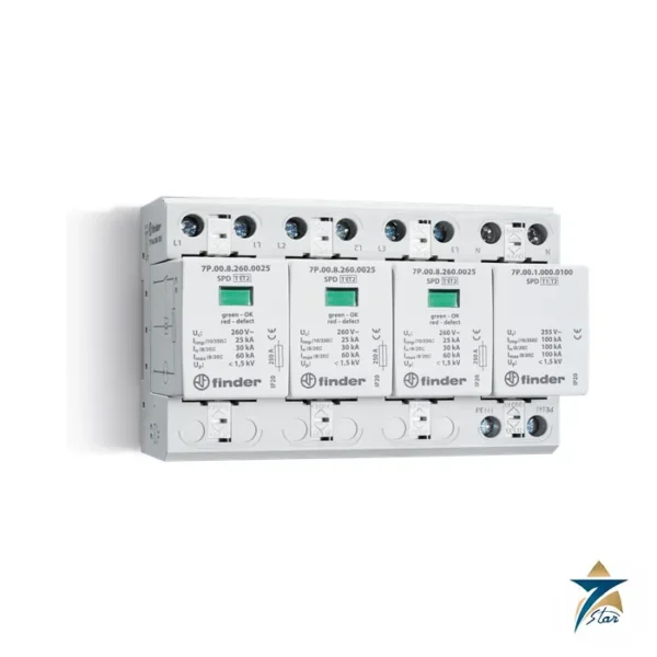
The Finder 7P.45.8.275.1020 is a Type 2 surge protection device for 230/400 V three-phase TN-S systems with neutral. It uses four combined varistor and encapsulated spark gap modules, one on each of L1, L2, L3 and neutral, so it protects line to neutral and neutral to PE and, according to the datasheet, works without leakage current and without following current. The voltage protection level is 1.2 kV for the L-N modules.
It is a distribution-board device, installed at the LPZ 1 to LPZ 2 boundary or higher, downstream of a Type 1 or Type 1+2 device (minimum distance 1 m according to the datasheet), to protect motors, drives, PLCs and sensitive electronics from induced overvoltage and switching transients. Each pole is 17.5 mm wide on a 35 mm DIN rail.
Technical specifications
| Parameter |
Specification |
| Manufacturer / series |
Finder, 7P series |
| Model |
7P.45.8.275.1020 |
| Type |
SPD Type 2 (EN 61643-11:2012) |
| System |
Three-phase 230/400 V TN-S with neutral |
| Protection scheme |
Varistor + GDT L1, L2, L3 to N; varistor + GDT N to PE |
| Nominal voltage UN |
230 V AC |
| Max. operating voltage UC |
275 V AC |
| Nominal discharge current In (8/20 us) |
20 kA |
| Max. discharge current Imax (8/20 us) |
25 kA |
| Voltage protection level Up |
1.2 kV |
| Leakage current IPE |
Below 4 uA |
| Following current |
No following current |
| TOV withstand |
120 min L-N 440 V AC; 5 s L-N 335 V AC |
| Response time ta |
100 ns |
| Short-circuit proof ISCCR |
35 kA rms |
| Max. overcurrent protection (gL/gG) |
125 A |
| Replacement module |
7P.40.8.275.0020 |
| Remote signalling contact |
1 CO (SPDT); 0.5 A AC / 0.1 A DC; 250 V AC / 30 V DC; connector 07P.01 included |
| Terminal wire size |
Solid 1 to 35 mm2; stranded 1 to 25 mm2; strip length 12 mm; torque 3 Nm |
| Ambient temperature |
-40 to +80 C |
| Protection degree / mounting |
IP 20; 35 mm rail EN 60715, 17.5 mm per pole |
Choosing between the Type 2 versions
The 7P.44.8.275.1020 and 7P.45.8.275.1020 are the two three-phase versions. The 7P.44 has three varistor + GDT modules for L1 to L3 and one spark gap for N to PE, which suits TT and TN-S systems, while the 7P.45 uses a fourth varistor + GDT module for N to PE and is specified for TN-S systems. Both versions are shown with box-clamp terminals and a remote contact module reporting healthy or replace. Finder also lists single-phase and other Type 2 versions in the 7P range.
Read the rated values table in the datasheet before choosing between the two versions, especially for a TT network where the N-PE rating matters.
Installation notes
A Type 2 SPD needs the right upstream protection. The datasheet gives a maximum overcurrent protection of 125 A gL/gG, short-circuit rating of 35 kA rms, and describes V-shape and T-shape connections. The conductor from the SPD to the equipotential bar should be as short as possible, with a copper cross section of at least 6 mm2 for Type 2 according to the datasheet. Where the downstream load current exceeds 125 A, connect the device in parallel. The red/green window on each module shows the state, and a failed module can be replaced without rewiring the base.
Key features of the 7P.45 four-module design
- Four identical plug-in protection modules, one per conductor, so every path to earth and between lines and neutral is clamped by a varistor working together with a gas discharge tube.
- The series combination of varistor and GDT keeps the leakage current to PE in the microampere range, which helps installations protected by residual current devices avoid nuisance tripping.
- No following current after a surge event, so the upstream fuse is not stressed by a mains-frequency current flowing through the device.
- Mechanical status window on each module: green means the module is healthy, red means it has reached end of life and must be exchanged.
- Changeover remote signalling contact for connection to a PLC input, a BMS or an alarm lamp, so a failed module is reported even in an unattended substation.
- Pluggable modules (spare part 7P.40.8.275.0020) allow insulation resistance testing of the installation after unplugging, without disconnecting the base wiring.
How the rated values relate to real installations
The nominal discharge current In of 20 kA is the 8/20 µs impulse the device can conduct repeatedly during the Type 2 test sequence, while Imax of 25 kA is the single highest impulse it is designed to divert. In practice most switching and induced surges in an industrial board are far below these values, so the useful service life depends on how often the network sees disturbances rather than on one large event.
The voltage protection level Up of 1.2 kV is the figure to compare with the impulse withstand category of the equipment being protected. Fixed equipment in a distribution board is normally category III or IV, while electronic loads such as drives and controllers are often more sensitive, which is why a Type 3 device close to those loads is a common addition. The UC value of 275 V AC gives margin above the nominal 230 V phase voltage for normal supply variation, and the stated TOV withstand covers temporary overvoltage such as a lost neutral for limited durations.
Selection checklist
| Question |
Why it matters |
| Is the earthing system TN-S, TN-C-S after the split point, or TT? |
The 7P.45 is specified for TN-S; for TT networks compare the 7P.44 with its dedicated N-PE spark gap. |
| Is there a Type 1 or Type 1+2 device at the service entrance? |
A Type 2 device is designed to work downstream of lightning current protection where the building is exposed to direct strikes. |
| What is the upstream fuse rating? |
Above 125 A gL/gG a dedicated back-up fuse is needed in the SPD branch. |
| Is remote monitoring required? |
This version includes the signalling contact; plan a spare input on the controller. |
| Are there long cable runs to sensitive loads? |
Over long runs, induced overvoltage can reappear, and a Type 3 device near the load may be justified. |
Installation and maintenance practice
Keep the total length of the connecting leads, from the phase conductors through the SPD to the earth bar, as short and straight as possible; every extra metre of wire adds inductive voltage drop that is added on top of the Up value during a fast impulse. Route the protected and unprotected conductors apart so that surge energy is not coupled back into the outgoing circuits. Tighten the box-clamp terminals to the torque given in the specification table and recheck them during the first planned shutdown.
During routine maintenance, inspect the status windows of all four modules and test the remote contact circuit. A module showing red should be replaced with the identical 7P.40.8.275.0020 cartridge; mixing module types on one base is not recommended. After a known lightning storm or a major switching event, a visual check of the indicators is a quick way to confirm that protection is still in place.
Use in Oman and GCC facilities
Long overhead feeders, generator changeover, large motor starting and capacitor bank switching are common sources of transients on industrial sites, pumping stations and telecom shelters in the region. The wide ambient temperature range of the device suits outdoor kiosks and non-air-conditioned panels, but board temperature should still be controlled, because high internal heat shortens the life of all electronic components. In dusty locations the IP 20 device must be installed inside a suitably rated enclosure.
What to include in an RFQ
- Full part number 7P.45.8.275.1020 and quantity, plus spare modules 7P.40.8.275.0020 if a maintenance stock is required.
- Network voltage, frequency and earthing arrangement.
- Upstream protective device rating and prospective short-circuit current at the board.
- Any project specification clause on SPD type, Up or approvals that must be confirmed.
Documents and quotation
The attached Finder 7P series datasheet contains the complete ordering list, SPD parameters explained, outline drawings and wiring examples; check the approvals printed for this type against your specification. When requesting a quotation for the 7P.45.8.275.1020, send the system voltage and earthing type, the expected line current, the upstream fuse and the number of units. See also Automation Accessories and the Phoenix Contact PLT-SEC-T3-230-FM Type 3 surge protection device for equipment-level protection.






Reviews
There are no reviews yet.