- Automation & ControlView all 2,690 products
- Automation Accessories
- AC Drives
- PLC & I/O Cards
- Industrial Communications
- Vibration Monitoring
- Controllers & Data Acquisition
- Isolator & Barrier
- Safety Switches & Guard Locking
- Motor Soft Starters
- CCTV & Security
- Encoders
- HMI Displays
- Servo Drives
- Pneumatic Cylinders
- Industrial Computers
- Machine Vision
- Automation Software
- Robotics








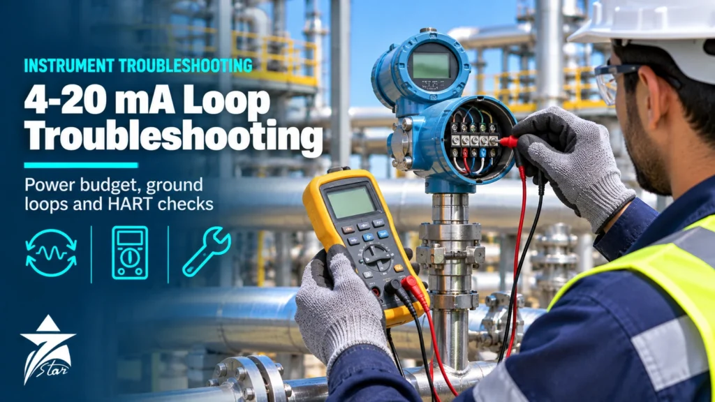
The 4-20 mA current loop is still the most common way to carry a measurement from a field instrument to a PLC or DCS. It is simple and robust, but when a reading is wrong the fault can be in the transmitter, the cable, a barrier or isolator, the input card or the configuration. Good 4-20 mA loop troubleshooting is a matter of checking these parts in a logical order instead of replacing the transmitter first. This guide gives that order, with the calculations and measurements a technician needs in the field.
How a 4-20 mA Loop Works
In a 2-wire loop the transmitter does not produce its own power. A DC supply, usually 24 V, drives current around a series circuit: supply, cable, transmitter, cable, and the receiving input, which measures the current across a resistor. The transmitter acts as a current regulator and sets the loop current between 4 and 20 mA in proportion to the measurement. Understanding this circuit is the basis of all 4-20 mA loop troubleshooting.
- 4 mA is the bottom of the range (live zero), so 0 mA clearly means a broken loop or no power.
- 20 mA is the top of the range.
- Because the signal is a current, cable resistance does not change the value, as long as the supply has enough voltage left to drive it.
- In a 4-wire instrument the transmitter has its own power supply and its output drives the current; the input card must then be passive.
Know the Fault Currents: NAMUR NE 43
Most modern transmitters follow NAMUR NE 43, which separates a real measurement from a failure signal:
| Loop current | Meaning under NE 43 |
|---|---|
| 3.8 to 20.5 mA | Valid measurement range, including small under- and over-range |
| 3.6 mA or less | Failure signal, low alarm (downscale) |
| 21 mA or more | Failure signal, high alarm (upscale) |
| Between 3.6 and 3.8 mA, or 20.5 and 21 mA | Not used, so that faults and measurements do not overlap |
So if the loop sits at about 3.6 mA or above 21 mA, the transmitter is usually reporting its own fault, such as a sensor break. Read its diagnostics before you touch the wiring. Check whether the alarm is set to high or low; the setting is configurable on most instruments.
Step 1: Start 4-20 mA Loop Troubleshooting With the Symptom
The current value already narrows down the cause. Use this table as the starting point for 4-20 mA loop troubleshooting:
| Symptom | Likely causes |
|---|---|
| 0 mA | Open circuit, no supply, blown fuse, reversed polarity, both devices passive |
| About 3.6 mA or below | Transmitter low alarm: sensor break or internal fault |
| Above 21 mA | Transmitter high alarm, or a short circuit bypassing the transmitter |
| Fixed at exactly 4 mA | HART multidrop address set, fixed-current or loop-test mode left on |
| Fixed at about 20.5 mA | Process above the upper range value, or wrong range configured |
| Correct mA but wrong value in the DCS | Range or scaling mismatch between transmitter and control system |
| Reading drops at high values | Insufficient loop voltage (power budget problem) |
| Noisy or jumping reading | Loose terminal, water in a junction box, poor shield earthing, noise coupling |
| Constant offset | Ground loop, leakage to earth, or input card calibration |
Step 2: Check the Loop Power Budget
In 4-20 mA loop troubleshooting, the power budget is the check most often skipped. Every 2-wire transmitter needs a minimum voltage across its terminals to work, often called lift-off voltage. The data sheet gives it, typically in the range of about 10 to 12 V for many HART transmitters. Everything else in the loop drops voltage: the input resistor, cable, barriers, isolators and any indicators. The rule is:
Supply voltage minus (total loop resistance x maximum current) must stay above the transmitter minimum voltage.
Use the maximum current the transmitter can produce, about 22 mA including alarm current, not 20 mA. Example: a 24 V supply and a transmitter that needs 12 V leaves 12 V for the rest of the loop. At 22 mA that allows (24 – 12) / 0.022 = about 545 ohms in total. A 250 ohm input resistor, a barrier and a long cable can use most of that.
- Add the input resistance of the card, the resistance of both cable conductors, and the voltage drop or resistance of each barrier, isolator and loop indicator.
- For copper cable, a 1.5 mm² conductor is roughly 12 ohms per kilometre. A loop 1 km long has 2 km of conductor.
- Measure the voltage at the transmitter terminals with the loop at a high current. If it falls below the minimum, the reading will stop rising or collapse.
- A power budget problem often appears only at the top of the range, so test at 20 mA, not just at 4 mA.
Step 3: Measure the Current Safely
There are three ways to read the loop current, from least to most intrusive:
- mA clamp meter: clamps around one wire and reads the current without breaking the loop. Good for a fast check; less accurate at low currents.
- Test terminals: many transmitters have test terminals across an internal diode. A meter on the mA range across them reads the loop current without disconnecting anything.
- Series measurement: open the loop and insert a meter on the mA range. Accurate, but the loop is broken briefly, so put the control loop in manual and inform operations first.
In hazardous areas, use only test equipment approved for the zone and follow the permit system. On intrinsically safe loops, check that the test equipment does not break the IS certification. Our guide to Zener barriers and galvanic isolators explains how these loops are built.
Step 4: Shunt Resistor Checks
Many input cards measure the current as a voltage across a 250 ohm resistor. Ohm’s law gives 1 V at 4 mA, 3 V at 12 mA and 5 V at 20 mA. Measuring the voltage across the resistor with a good voltmeter is a quick way to check the current without opening the loop. If the voltage is correct but the DCS shows a different value, the fault is in the card or in the scaling, not in the field. If you add a temporary resistor for testing, use a precision resistor and include it in the power budget.
Step 5: Active and Passive Devices
Exactly one device in the loop must supply power. Problems appear when this is wrong:
- Two passive devices (a 2-wire transmitter on a passive input): no power source, 0 mA.
- Two active devices (a 4-wire transmitter on an input that also supplies loop power): the two supplies fight; the reading is wrong and parts may be damaged.
- Check the input card or isolator data sheet: many cards can be set to active or passive per channel by wiring or configuration.
Step 6: Ground Loops and Noise
Ground loops are among the hardest faults in 4-20 mA loop troubleshooting. A ground loop happens when the signal circuit is connected to earth at two points with different potentials. A circulating current then adds to or subtracts from the signal and produces an offset or noise. Signs include readings that change when a motor starts, a different value at the transmitter and in the DCS, or an offset that disappears when the field device is disconnected from earth.
- Earth the cable shield at one end only, normally in the control room or marshalling cabinet, unless the site standard says otherwise.
- Keep the signal circuit floating, or earth it at one point only.
- Check transmitters whose housing or signal circuit is connected to local earth.
- Install a galvanic signal isolator to break the loop where two earth points cannot be avoided.
- Separate signal cables from power cables and VFD motor cables, and use twisted, shielded pairs.
- Check insulation resistance of the cable to earth with the instrument disconnected, if the site procedure allows.
Long field cables are also exposed to lightning and switching surges; protect them with signal-line SPDs at both ends where the risk is high.
Step 7: HART Signal Problems
HART places a small digital signal on top of the 4-20 mA current, using two tones at 1,200 Hz and 2,200 Hz with an amplitude of about ±0.5 mA. The average value is zero, so it does not change the analog reading. HART problems have their own causes:
- Too little loop resistance: HART needs a minimum resistance in the loop, typically 250 ohms, for the communicator to see the signal.
- Isolators and barriers that are not HART transparent block the digital signal; check the data sheet.
- Filtering capacitors on some input cards or indicators can weaken the signal.
- Noise from VFD cables and poor shielding causes communication errors.
- A multidrop address other than 0 fixes the current at 4 mA on many devices; check the polling address.
- Compare the digital primary value read by the communicator with the analog current. If they agree but the DCS does not, the problem is downstream of the transmitter.
Our article on industrial communication protocols explains HART alongside fieldbus and Ethernet protocols, and the smart valve positioner guide covers HART diagnostics on the output side of the loop.
Step 8: Loop Check With a Calibrator
A loop calibrator is the main tool for 4-20 mA loop troubleshooting and commissioning. It can source current (simulating the transmitter), simulate a 2-wire transmitter while the loop supplies the power, or read current while it supplies 24 V itself. A full loop check usually means:
- Simulate 4, 8, 12, 16 and 20 mA at the field end and confirm the value in the DCS at each point.
- Use the transmitter loop-test (fixed current) function through HART as an alternative.
- Check alarms and trips at the configured values.
- Return the transmitter to normal mode and remove any fixed current settings afterwards.
- Record the results as found and as left.
For transmitter configuration and sensor issues, see our guide on temperature transmitter selection, which covers HART and sensor matching.
Loop Calibrators, Isolators and Supplies From Our Catalog
Examples of products used for 4-20 mA loop troubleshooting, loop testing and loop protection in our catalog. Each link goes to the product page.
| Product | Type | Typical use |
|---|---|---|
| Fluke 789 ProcessMeter Multimeter and mA Loop Calibrator | Multimeter with mA source and loop power | Field checks and loop powering |
| Fluke 725 Multifunction Process Calibrator | Multifunction calibrator | mA, voltage, temperature and pressure checks |
| Beamex MC2 Hand-Held Process Calibrator | Hand-held process calibrator | Field calibration and loop checks |
| Additel ADT226 Multifunction Documenting Process Calibrator | Documenting calibrator | Recorded loop checks and calibration |
| Additel ADT295 HART, Fieldbus and Profibus PA Communicator | Communicator | HART configuration and diagnostics |
| Pepperl+Fuchs HiC2025 SMART Transmitter Power Supply | Transmitter power supply / isolator | Powering field transmitters from the DCS |
| Pepperl+Fuchs KFD2-STC5-1 SMART Transmitter Power Supply | Transmitter power supply / isolator | Hazardous area transmitter loops |
| MTL 5043 Repeater Power Supply, Dual Output (4-20 mA) | Repeater power supply | Splitting one loop to two receivers |
| Phoenix Contact MACX MCR-UI-UI-NC 3-Way Isolating Amplifier | Signal isolator | Breaking ground loops |
| Phoenix Contact MINI MCR-2-UI-UI 3-Way Signal Conditioner (2902037) | Signal conditioner | Isolation and signal conversion |
| Moore Industries SIX Signal Isolator, Converter and Repeater | Signal isolator | Isolation and repeating of 4-20 mA signals |
| Phoenix Contact 2906799 TTC-6-2X1-24DC-UT Surge Protector | Signal surge protector | Long field cables on 4-20 mA loops |
Browse more in our isolator and barrier category and our process calibrators category. To get a quotation, send the signal type, number of channels, hazardous area requirements, HART needs and the model of any existing device through our quote request form or to [email protected].
Sourcing Loop Test and Signal Equipment in Oman Through Seven Star LLC
Seven Star LLC is an independent supplier in Oman of instrumentation, calibration and automation products. We quote loop calibrators, HART communicators, signal isolators, barriers and transmitter power supplies from manufacturers such as Fluke, Beamex, Additel, Pepperl+Fuchs, MTL, Phoenix Contact and Moore Industries, and we can match an installed module by part number. Specifications, approvals and lead time are confirmed against the manufacturer data at quotation.
Frequently asked questions
What does 0 mA mean in a 4-20 mA loop?
0 mA usually means the loop is open or has no power: a broken wire, loose terminal, blown fuse, missing supply or reversed polarity. It can also mean that two passive devices are connected, so nothing supplies the loop. Because the range starts at 4 mA, 0 mA is never a valid measurement.
Why is my transmitter stuck at 3.6 mA or above 21 mA?
Under NAMUR NE 43, a current of 3.6 mA or less, or 21 mA or more, is a failure signal. The transmitter is reporting its own fault, for example a sensor break. Read the transmitter diagnostics with a HART communicator before checking the wiring.
How do I calculate the loop power budget?
Subtract the transmitter minimum voltage from the supply voltage, then divide by the maximum loop current, about 0.022 A. The result is the maximum total resistance of input card, cable, barriers and indicators. For example, (24 V - 12 V) / 0.022 A is about 545 ohms.
How can I measure loop current without breaking the loop?
Use an mA clamp meter, connect a meter across the transmitter test terminals if it has them, or measure the voltage across the 250 ohm input resistor and calculate the current. 1 V means 4 mA and 5 V means 20 mA.
How do I fix a ground loop in a 4-20 mA circuit?
Earth the cable shield at one end only, keep the signal circuit earthed at a single point, separate signal and power cables, and install a galvanic signal isolator where two earth points cannot be avoided.
Who supplies loop calibrators and signal isolators in Oman?
Seven Star LLC is an independent supplier in Oman that quotes loop calibrators, HART communicators, signal isolators and transmitter power supplies from Fluke, Beamex, Additel, Pepperl+Fuchs, MTL, Phoenix Contact and Moore Industries. Send your requirements through the quote request form or to [email protected].
Was this guide helpful?One click helps us write better guides for engineers.
Thank you! Glad it helped. Need this equipment for your project? Request a quotation
Thank you. We will use this to improve the guide.