- Automation & ControlView all 1,599 products
- AC Drives
- Industrial Communications
- PLC & I/O Cards
- Vibration Monitoring
- Automation Accessories
- Controllers & Data Acquisition
- CCTV & Security
- Safety Switches & Guard Locking
- Encoders
- Industrial Computers
- Servo Drives
- Motor Soft Starters
- HMI Displays
- Pneumatic Cylinders
- Isolator & Barrier
- Automation Software
- Machine Vision
- Robotics
















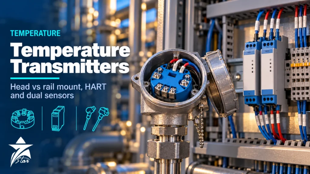
Temperature transmitter selection looks simple until the loop goes live and the reading is two degrees off, noisy, or drops out every time a nearby motor starts. The transmitter converts a small RTD resistance or thermocouple millivolt signal into a robust output, applies linearisation and diagnostics, and often decides whether the measurement is trusted by operators. This guide covers the main decisions: mounting style, input type, protocol, accuracy budget, dual-sensor functions, Callendar–Van Dusen sensor matching, hazardous-area and GCC installation details, and the data you should put on the datasheet.
Why Use a Transmitter at All
Some systems wire RTDs and thermocouples straight into DCS or PLC input cards. That works in a cabinet next to the equipment, but it has drawbacks in the field. Thermocouple signals are only microvolts per degree and are easily disturbed by electrical noise; thermocouple extension cable must match the sensor type and costs more than ordinary instrument cable; and long RTD leads add resistance error. A transmitter close to the sensor converts the signal to 4–20 mA or a digital protocol, removes most of these problems, and adds diagnostics that a simple input card cannot provide.
Mounting Styles Compared
| Style | Where it sits | Strengths | Limitations |
|---|---|---|---|
| Head-mount | Inside the sensor connection head (DIN form B type) | Shortest sensor wiring, low cost, compact | No display in most heads; electronics exposed to the head’s temperature |
| Field-mount | Separate dual-compartment housing on the well or a stand | Local display, separate terminal compartment, flameproof versions, better transient protection | Higher cost and size |
| Rail-mount | 35 mm DIN rail in a cabinet or junction box | Neat for many points, easy access, protected environment | Long sensor or extension wiring to the cabinet; more noise exposure |
| Multi-input | Field or cabinet unit with several inputs on fieldbus or wireless | Low cost per point for tank farms, heaters, bearing temperatures | Shared electronics; usually not for critical control |
For most process measurements a head-mount or field-mount transmitter is the best technical choice. Rail-mount suits skids, packaged equipment and analyser shelters where sensors are close to the panel.
Input Types and Wiring
Universal transmitters accept RTDs (Pt100, Pt1000, Ni120 and others), thermocouples (types J, K, T, E, N, R, S, B), millivolt and ohm inputs. The choice of sensor is covered in our RTD vs thermocouple guide; for the transmitter the important points are wiring and cold junction compensation.
- RTD 2-wire: lead resistance adds directly to the reading. A Pt100 changes by about 0.385 Ω/°C, so 1 Ω of total lead resistance means roughly 2.6 °C error.
- RTD 3-wire: compensates lead resistance if the leads are equal; the standard choice in industry.
- RTD 4-wire: fully eliminates lead resistance; used for high-accuracy and custody-related points.
- Thermocouples: the transmitter measures its own terminal temperature for cold junction compensation, so CJC accuracy is part of the error budget; keep the transmitter away from heat sources that create gradients across the terminals.
Output and Protocol
Most new installations still use 4–20 mA with HART, which gives an analog signal for the control system plus digital access to configuration, diagnostics and secondary variables. FOUNDATION Fieldbus and PROFIBUS PA suit plants already built around those systems, and WirelessHART suits remote or retrofit points where cabling is expensive. Our industrial communication protocols guide compares them in detail.
Two NAMUR recommendations are worth specifying:
- NE43: the measurement signal stays between 3.8 and 20.5 mA, and failure is signalled at 3.6 mA or below, or 21.0 mA or above. State upscale or downscale failure on the datasheet.
- NE107: a standardised set of device status categories (failure, function check, out of specification, maintenance required) that makes diagnostics consistent across vendors.
Building a Realistic Accuracy Budget
Transmitter brochures quote digital accuracy, but the measurement error is a combination of several sources. Engineers typically combine independent errors as the root of the sum of squares.
- Sensor tolerance: for a Pt100 to IEC 60751, Class A is ±(0.15 + 0.002·|t|) °C and Class B is ±(0.3 + 0.005·|t|) °C. At 100 °C that is ±0.35 °C for Class A and ±0.8 °C for Class B.
- Transmitter digital accuracy for the input type, from the datasheet.
- D/A accuracy of the analog output, if the 4–20 mA signal is used.
- Ambient temperature effect on the electronics, which matters in hot outdoor installations.
- Long-term stability of both sensor and transmitter.
- Installation errors: stem conduction, response lag, lead resistance with 2-wire connection.
At moderate temperatures the sensor tolerance is often the largest single term, which is why sensor matching is so effective.
As an illustration, consider a Class B Pt100 at 100 °C (±0.8 °C) combined with a transmitter whose digital and analog terms together amount to a few tenths of a degree. The root-sum-square total is still dominated by the sensor, so buying a more expensive transmitter barely changes the result. Upgrading to a Class A sensor, or matching the sensor to the transmitter, has a much larger effect. Always check which term dominates before paying for extra accuracy in the wrong component.
Callendar–Van Dusen Sensor Matching
The resistance of a platinum RTD follows the Callendar–Van Dusen (CVD) equation: R(t) = R0 [1 + A·t + B·t² + C·(t − 100)·t³], where the C term applies only below 0 °C. IEC 60751 defines standard coefficients for the 0.00385 curve: A = 3.9083 × 10⁻³, B = −5.775 × 10⁻⁷ and C = −4.183 × 10⁻¹². Real sensors deviate slightly from these values, and the tolerance class only states how far they may deviate.
When a sensor is calibrated at several temperatures, the laboratory can calculate its own R0, A, B and C. Entering these constants into a transmitter that supports CVD input makes it linearise using the actual sensor curve. The interchangeability error largely disappears, leaving calibration uncertainty, stability and transmitter error. Emerson and other manufacturers describe this matched-system approach as improving accuracy well beyond Class A or Class B tolerance.
Practical points:
- Order the sensor with a calibration certificate that states the CVD constants, or have it calibrated before installation.
- Keep sensor and transmitter together as a matched pair, and record the pairing in the maintenance system.
- When the sensor is replaced, the new constants must be entered; otherwise the matching is lost.
- If CVD entry is not available, a two-point sensor trim against a reference achieves part of the benefit over a limited range.
Include matched pairs in your instrument calibration program so that re-verification uses the same reference points.
Dual-Sensor Transmitters
A dual-input transmitter connected to a dual-element sensor improves both reliability and confidence in the reading. Typical functions are:
- Hot backup: automatic switch to the second sensor if the primary fails, with an alert.
- Sensor drift alert: a warning when the difference between the two sensors exceeds a set limit.
- Average or differential output: for large vessels, heat exchangers or bearing pairs.
- First-good or minimum/maximum selection for specific control strategies.
Dual-element sensors in one well share the same installation errors, so drift alerts detect sensor ageing rather than poor immersion. For safety instrumented functions, independent wells and transmitters are normally used to meet architecture requirements, and the transmitter should carry IEC 61508 certification or proven-in-use justification for the required SIL capability.
Diagnostics Worth Having
- Open and short sensor detection with configurable failure current.
- Thermocouple degradation monitoring, which tracks loop resistance as the junction ages.
- Minimum and maximum tracking of process and electronics temperature.
- Galvanic isolation between input and output, essential with grounded thermocouples to avoid ground loops.
- Write protection and configuration change counters for audit trails.
Hazardous Areas and Electrical Protection
Head-mount transmitters are commonly certified intrinsically safe (Ex ia) and installed with barriers or isolators; field-mount housings are also available as flameproof (Ex d) with Ex e or Ex d terminal compartments. Match the certificate to the area classification and the system’s barrier philosophy. Transient protection is worth specifying for field-mount units on tall structures, tank roofs and open pipe racks exposed to lightning.
GCC Installation Notes
Electronics in most industrial temperature transmitters are rated up to around 85 °C ambient. In Oman and the GCC, a connection head mounted directly on a hot pipe and exposed to full summer sun can approach that limit. Use extension necks to move the head away from hot lines, fit sunshades on field housings, and consider remote mounting with a short sensor cable for very hot services. Offshore and coastal sites benefit from 316 stainless housings and properly sealed cable glands to resist salt-laden air and humidity, and dusty desert sites need enclosures rated IP66/IP67 with intact cover seals.
Common Temperature Transmitter Selection Mistakes
- Using 2-wire RTD connections with long leads.
- Mismatched thermocouple type and extension cable, or reversed polarity.
- Not configuring the NE43 failure direction or the DCS alarm limits to match it.
- Replacing a matched sensor without updating the CVD constants.
- Grounding a thermocouple at both the sensor and the input card on a non-isolated transmitter.
- Mounting heads on hot pipes without an extension neck.
Temperature Transmitter Selection Checklist
- Sensor type, connection (2/3/4-wire), tolerance class and CVD constants if available.
- Measurement range and required total accuracy.
- Mounting: head, field (with or without display) or DIN rail.
- Output: 4–20 mA HART, FOUNDATION Fieldbus, PROFIBUS PA or WirelessHART.
- Single or dual input, and which dual-sensor functions are needed.
- NE43 failure direction, isolation requirements and SIL needs.
- Hazardous-area certification, enclosure material and ingress rating.
- Ambient temperature range and existing make and model if replacing.
Temperature Transmitters We Supply
These examples cover head-mount, field-mount, wireless and safety-rated transmitters.
| Product | Type | Where it fits |
|---|---|---|
| Rosemount 3144P Temperature Transmitter | Field-mount temperature transmitter | Critical loops that need high accuracy and diagnostics. |
| Yokogawa YTA710 Temperature Transmitter | Temperature transmitter | General process temperature with HART. |
| PR Electronics 5335D 2-Wire HART Temperature Transmitter | 2-wire HART transmitter | Head-mount installation in sensor connection heads. |
| Moore Industries STZ Functional Safety Dual Input Smart HART Temperature Transmitter | Dual-input safety transmitter | Safety loops and sensor redundancy. |
| Rosemount 648 Wireless Temperature Transmitter | Wireless temperature transmitter | Points where running cable would cost more than the transmitter. |
| ABB TTF300.S3.C.2.H.BF-C4.C Field-Mount Temperature Transmitter | Field-mount temperature transmitter | Field installation in harsh conditions. |
Send the sensor type, range, output and protocol, mounting style and hazardous-area marking through our quote request form.
Sourcing Temperature Transmitters Through Seven Star LLC
Seven Star LLC supplies temperature transmitters, sensors, thermowells and isolators on request for customers across Oman and the GCC, from manufacturers such as Emerson, Endress+Hauser, Yokogawa, ABB and Siemens. We help with selection and with cross-checking model codes and part numbers; availability and lead time are confirmed at quotation. See our temperature instrumentation and isolators and barriers categories.
Send us your temperature transmitter datasheet, the nameplate or model code of the existing unit, or an RFQ listing sensor type and protocol, and we will prepare a matched quotation.
Frequently asked questions
Should I use a head-mount or a rail-mount temperature transmitter?
Head-mount transmitters sit in the sensor connection head, keep sensor wiring very short and send a robust 4–20 mA signal back to the control room. Rail-mount transmitters sit in a cabinet, which suits clean or protected locations and many inputs, but the sensor or thermocouple extension cable has to run all the way to the cabinet. For most process points in the field, head-mount or field-mount units give better noise immunity and lower wiring cost.
What is Callendar–Van Dusen sensor matching?
Every RTD deviates slightly from the standard IEC 60751 curve. When a sensor is calibrated, its individual Callendar–Van Dusen constants (R0, A, B and C) are calculated, and entering them into a compatible transmitter makes it use that sensor's real curve. This removes most of the sensor interchangeability error and can make the system considerably more accurate than the sensor's tolerance class alone.
What does a dual-sensor temperature transmitter do?
It accepts two sensors, usually two elements in the same thermowell, and can switch automatically to the second if the first fails (hot backup). It can also alarm when the two readings drift apart, output their average or difference, and report which sensor is in use. This improves availability on critical loops and gives early warning of sensor drift.
How much error does a 2-wire RTD connection add?
A Pt100 changes by about 0.385 Ω per °C, so lead resistance appears directly as temperature error. One ohm of total lead resistance adds about 2.6 °C of error, which is why 3-wire or 4-wire connections are used for anything other than very short leads. With a head-mount transmitter the leads are short, but 3-wire or 4-wire is still preferred.
Which NAMUR NE43 settings should a temperature transmitter use?
Under NAMUR NE43 the measurement signal stays between 3.8 and 20.5 mA, and failure is signalled at 3.6 mA or below, or 21.0 mA or above. Most modern transmitters can be configured for upscale or downscale failure. Choose the direction that drives the process to a safe state and make sure the DCS alarms are set to recognise those currents.
Do I need a SIL-certified temperature transmitter?
Only if the transmitter is part of a safety instrumented function. In that case it should be certified or proven-in-use to IEC 61508 for the required SIL capability, and configured as described in its safety manual. For control and monitoring loops a standard transmitter is sufficient.
Was this guide helpful?One click helps us write better guides for engineers.
Thank you! Glad it helped. Need this equipment for your project? Request a quotation
Thank you. We will use this to improve the guide.