- AC Drives
- Industrial Communications
- PLC & I/O Cards
- Automation Accessories
- Vibration Monitoring
- Controllers & Data Acquisition
- CCTV & Security
- Safety Switches & Guard Locking
- Encoders
- Industrial Computers
- Servo Drives
- Motor Soft Starters
- HMI Displays
- Pneumatic Cylinders
- Isolator & Barrier
- Automation Software
- Machine Vision
- Robotics
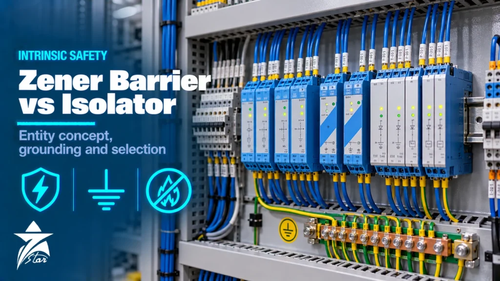
Choosing between a zener barrier vs galvanic isolator is one of the first decisions when designing an intrinsically safe (IS) loop for a hazardous area. Both are associated apparatus: they sit in the safe area (or in a protected enclosure in Zone 2) and limit the energy that can reach the field wiring so that a spark or hot surface cannot ignite a flammable atmosphere. They achieve this in very different ways, with different consequences for earthing, accuracy, field device compatibility, cost and maintenance. This guide explains how each works, how to carry out an entity check, what the earthing rules mean in practice and how to select the right interface for each signal type.
Intrinsic Safety in Brief
Intrinsic safety is a protection concept that limits electrical and thermal energy in a circuit to a level below what is needed to ignite a specific gas, vapour or dust. It is defined internationally in IEC 60079-11 (equipment), IEC 60079-25 (IS systems) and IEC 60079-14 (installation), with equivalent North American requirements in the NEC and ANSI/UL standards.
Key terms:
- Intrinsically safe apparatus: the field device, such as a transmitter, solenoid valve or switch, marked for example Ex ia IIC T4 Ga.
- Associated apparatus: the barrier or isolator, marked with the protection level in square brackets, for example [Ex ia Ga] IIC, meaning it contains IS circuits but is installed outside the hazardous area unless it has an additional protection concept.
- Protection levels: ia remains safe with two countable faults and is suitable for Zone 0; ib with one fault, suitable for Zone 1; ic in normal operation, suitable for Zone 2.
- Gas groups: IIC (hydrogen, acetylene) is the most demanding, then IIB (for example ethylene) and IIA (for example propane). Dust groups are IIIA, IIIB and IIIC.
For a broader overview of zones, gas groups and temperature classes, see our hazardous area classification guide.
How a Zener Barrier Works
A shunt-diode safety barrier, usually called a Zener barrier, is a passive network: a fuse, Zener diodes and a current-limiting resistor. In normal operation the Zener diodes do not conduct and the signal passes through the series resistance. If a fault in the safe area applies a high voltage, the Zeners conduct and clamp the voltage, shunting the fault current to earth until the fuse blows. The resistor limits the current that can flow into the hazardous area.
This design has consequences:
- The IS earth is part of the safety function. Without a sound earth, the fault current has nowhere to go and the hazardous-area voltage is not limited.
- The barrier is referenced to earth, so the field circuit is effectively earthed at the barrier. Field devices must normally be isolated from earth.
- Series resistance causes a voltage drop. In a 4-20 mA loop this reduces the voltage available at the transmitter, which must be checked against the transmitter’s minimum supply voltage at 20 mA.
- Barriers are simple and compact, with no power supply of their own in most cases, and they are generally the lower-cost option.
How a Galvanic Isolator Works
A galvanic isolator (also called an isolated barrier or isolating interface) separates the hazardous-area and safe-area circuits with a transformer, optocoupler or relay. Energy limitation is provided on the hazardous-area side by internal circuitry, and the isolation itself prevents a safe-area fault from reaching the field wiring. Typical characteristics:
- No IS earth is required for safety, which removes the main maintenance burden of barriers.
- Earthed field devices can be used, and ground loops between the field and the control system are broken.
- Active signal conditioning: isolators can repeat 4-20 mA signals, power two-wire transmitters, convert thermocouple or RTD inputs, provide relay or transistor outputs for switches and NAMUR sensors, and drive solenoid valves.
- They need a power supply, normally 24 V DC, often distributed by a power rail bus, and they dissipate more heat than barriers.
- Higher unit cost, but often fewer modules overall because two channels and extra functions are common.
Zener Barrier vs Galvanic Isolator: Side-by-Side Comparison
| Feature | Zener barrier | Galvanic isolator |
|---|---|---|
| — | — | — |
| Safety principle | Diodes, resistor and fuse divert fault energy to earth | Isolation plus internal energy limitation |
| IS earth | Mandatory, low resistance and verified | Not required for safety |
| Earthed field devices | Generally not suitable | Suitable |
| Power supply | Usually none | 24 V DC supply required |
| Voltage drop in loop | Significant series resistance | Isolator supplies the transmitter |
| Signal functions | Pass-through only | Repeating, conversion, alarms, relays |
| Ground loop and noise | Common reference with earth | Breaks ground loops |
| Typical cost per channel | Lower | Higher |
| Maintenance | Regular earth testing | Fewer earthing checks |
The Entity Concept
Regardless of which interface you use, the loop must be verified as an IS system. The entity concept compares the certified output parameters of the associated apparatus with the input parameters of the field device and the cable. The conditions are:
- Uo (barrier output voltage) is less than or equal to Ui (device maximum input voltage).
- Io (output current) is less than or equal to Ii (input current).
- Po (output power) is less than or equal to Pi (input power).
- Co (allowed capacitance) is greater than or equal to Ci of the device plus the cable capacitance.
- Lo (allowed inductance) is greater than or equal to Li of the device plus the cable inductance, or the cable L/R ratio is within the allowed L/R.
North American documentation uses Voc or Vt, Isc or It, Ca and La for the barrier and Vmax, Imax, Ci and Li for the field device, but the logic is the same. Where actual cable data is not known, designers commonly use default values of about 200 pF per metre and 1 microhenry per metre, but manufacturer data for the installed cable gives a more accurate result.
The IIC gas group allows much less capacitance and inductance than IIB, so long cable runs and devices with significant internal capacitance can fail the check in IIC while passing in IIB. Document the entity calculation for every loop type and keep it with the loop drawings; inspectors will expect to see it.
Simple apparatus
Devices that neither generate nor store significant energy, such as switch contacts, thermocouples, RTDs and LEDs, can be treated as simple apparatus under IEC 60079-11 (not exceeding 1.5 V, 100 mA and 25 mW). They do not need their own certificate, but they still need to be considered in the system: a thermocouple can generate voltage, and its temperature classification must suit the area.
Earthing and Installation Rules
For Zener barriers, the IS earth is critical. Good practice includes:
- An insulated IS earth bar, connected by two independent conductors to the main plant earth, with each conductor sized to carry the fault current.
- A resistance between the barrier earth and the main earth point commonly specified as not more than 1 ohm, measured at commissioning and at regular intervals.
- Barriers mounted on an earthed DIN rail or bus bar designed for that purpose, as instructed by the manufacturer.
For both technologies:
- Keep IS and non-IS wiring separate, using separate cable trays or partitions and separated terminals. A clearance of about 50 mm between IS and non-IS terminals is a typical requirement.
- Identify IS cables and terminals, usually with light blue colour coding.
- Earth cable screens at one point, as defined by the system design, to avoid circulating currents.
- Check that associated apparatus mounted in Zone 2 carries a suitable additional marking, such as Ex ec or Ex nA, and is installed in an appropriate enclosure.
Selecting by Signal Type
- Analogue inputs (4-20 mA transmitters): isolators that power the transmitter and repeat the signal avoid voltage-drop problems and are the usual choice for new systems. Zener barriers remain common in existing installations and where cost and panel space dominate. Confirm HART transparency where needed; see our article on HART, fieldbus and Modbus protocols.
- Digital inputs (contacts and NAMUR sensors): switch amplifiers with relay or transistor outputs and line-fault detection are standard.
- Analogue outputs to valve positioners: isolators designed for output loops, often with HART pass-through.
- Solenoid valves and alarms: isolated output drivers matched to the coil’s Ui, Ii and Pi, and to its minimum operating current.
- Temperature: isolators with thermocouple or RTD inputs and 4-20 mA outputs, with cold-junction compensation for thermocouples.
- Fieldbus: FISCO or Entity power supplies and segment barriers designed for Foundation Fieldbus or PROFIBUS PA.
Common Mistakes
- Mixing up barrier polarity or using a barrier rated for the wrong gas group.
- Connecting an earthed thermocouple or a field device with internal earth connection to a Zener barrier.
- Ignoring the series resistance, so the transmitter has too little voltage at full scale.
- Losing the IS earth during panel modifications, or never retesting it.
- Replacing an isolator with a non-IS signal conditioner of similar appearance.
- Using a device whose entity parameters were never checked with the actual cable length.
Operating in GCC Conditions
Oil and gas, petrochemical and gas processing plants in Oman and across the GCC rely heavily on IS loops. Control rooms are usually air conditioned, but remote instrument shelters and marshalling cabinets can see high internal temperatures, so check the maximum ambient rating of the interface modules and allow for their heat dissipation, which is higher for isolators. Dusty environments make sealed cabinets and regular inspection of terminals important. Many operators follow IEC-based Ex certification schemes, while some packaged equipment arrives with North American marking; check that the documentation matches the plant’s requirements.
Zener Barrier vs Galvanic Isolator Selection Checklist
- Zone, gas group and temperature class of the field device location
- Required protection level: ia, ib or ic
- Signal type and direction, including HART or fieldbus needs
- Entity parameters of the field device and cable data
- Field device earthing: isolated or earthed
- Loop voltage budget at full scale
- Availability and condition of an IS earth
- Mounting location: safe area or Zone 2 cabinet
- Power supply, heat dissipation and panel space
- Certification scheme required: IECEx, ATEX or North American
Intrinsic Safety Interfaces We Supply
These are examples of isolated interfaces and fieldbus barriers from our catalogue, covering the main signal types discussed above.
| Product | Type | Where it fits |
|---|---|---|
| Eaton MTL5541 Repeater Power Supply | Isolating repeater power supply | Powering 2-wire 4-20 mA transmitters in hazardous areas. |
| Phoenix Contact MACX MCR-EX-SL-RPSSI-I Signal Isolator | Isolated signal repeater | 4-20 mA and HART transmitter loops. |
| Pepperl+Fuchs KFD2-SR2-Ex2.W K-System Isolated Switch Amplifier | Isolated switch amplifier | NAMUR proximity sensors and dry contacts in the field. |
| Pepperl+Fuchs KFD2-UT2-Ex2 Universal Temperature Converter | Universal temperature converter | RTD and thermocouple inputs from the hazardous area. |
| MTL5576-THC Temperature Isolator Module | Temperature isolator | Temperature inputs into a DCS or PLC. |
| MTL 9370-FB2 Intrinsically Safe Fieldbus Barrier | Intrinsically safe fieldbus barrier | Foundation Fieldbus and PROFIBUS PA segments into Zone 1. |
To select an interface, send the field device, signal type, number of channels and the area classification through our quote request form.
Sourcing Zener Barriers and Galvanic Isolators Through Seven Star LLC
Seven Star LLC supplies isolators and barriers on request, along with field instruments from our pressure instrumentation range and PLC and I/O cards, from manufacturers such as Pepperl+Fuchs, MTL and Phoenix Contact. We help with selection and cross-checking part numbers against your existing loops, and availability and lead time are confirmed at quotation.
Replacing a barrier or upgrading to isolators? Send us the module nameplate or part number, the field device datasheet and the signal type, and we will prepare a matched quotation.
Frequently asked questions
What is the main difference between a Zener barrier and a galvanic isolator?
A Zener barrier limits voltage and current with Zener diodes, a resistor and a fuse, and diverts fault energy to a dedicated intrinsic safety earth. A galvanic isolator separates the hazardous-area circuit from the safe-area circuit with a transformer, optocoupler or similar barrier, so it does not need an IS earth connection to remain safe.
Does a Zener barrier need a special earth?
Yes. A shunt-diode barrier is only safe when its earth terminal is connected to a reliable, low-resistance intrinsic safety earth, usually with redundant conductors back to the main earth point. Installation standards commonly specify a resistance of not more than 1 ohm, and the earth must be checked periodically.
What does the entity concept check?
It compares the output parameters of the associated apparatus (Uo, Io, Po, Co, Lo) with the input parameters of the field device (Ui, Ii, Pi, Ci, Li). The barrier's Uo, Io and Po must not exceed the device's Ui, Ii and Pi, and the allowed Co and Lo must be at least the device's Ci and Li plus the capacitance and inductance of the cable.
Can I use a Zener barrier with an earthed field device?
Generally not. A Zener barrier is referenced to earth, so an earthed sensor such as a grounded thermocouple creates a second earth path that can cause measurement errors and may undermine the safety concept. Galvanic isolators are preferred for earthed or poorly isolated field devices.
Do HART signals pass through barriers and isolators?
Many barriers and isolators are designed to pass HART communication on 4-20 mA loops, but not all are. Check that the model is listed as HART-transparent, and allow for the series resistance of a Zener barrier when calculating the loop voltage available at the transmitter.
What is simple apparatus?
Simple apparatus is a passive or low-energy device, such as a switch contact, thermocouple, RTD or LED, that does not generate or store more than very small amounts of energy as defined in IEC 60079-11. It can be connected to an IS circuit without its own certificate, provided the associated apparatus and the system design account for it.
Was this guide helpful?One click helps us write better guides for engineers.
Thank you! Glad it helped. Need this equipment for your project? Request a quotation
Thank you. We will use this to improve the guide.