- Automation & ControlView all 1,596 products
- AC Drives
- Industrial Communications
- PLC & I/O Cards
- Vibration Monitoring
- Automation Accessories
- Controllers & Data Acquisition
- CCTV & Security
- Safety Switches & Guard Locking
- Encoders
- Industrial Computers
- Servo Drives
- Motor Soft Starters
- HMI Displays
- Pneumatic Cylinders
- Isolator & Barrier
- Automation Software
- Machine Vision
- Robotics
















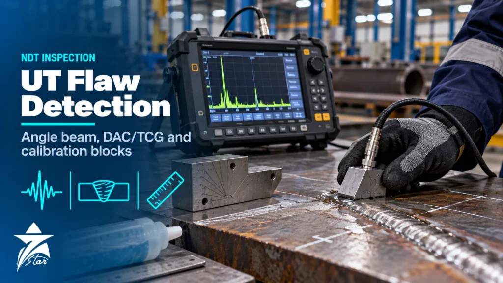
Ultrasonic flaw detection is the volumetric weld inspection method most fabrication and maintenance teams rely on when radiography is slow, hazardous to schedule or simply impossible on thick sections. It finds lack of fusion, cracks, slag and root defects in butt and fillet welds, but only if the probe angle, the time base, the sensitivity reference and the scanning pattern are all set up correctly. A flaw detector that is badly calibrated does not fail loudly; it simply reports a clean weld. This guide covers how pulse-echo flaw detection works, angle-beam geometry, calibration on IIW-type blocks, distance amplitude correction (DAC) and time corrected gain (TCG), weld scanning technique, sizing and the mistakes that most often let defects through.
How Pulse-Echo Flaw Detection Works
A piezoelectric transducer converts a short electrical pulse into a burst of ultrasound, typically between 1 and 5 MHz for steel welds. The sound travels through the part, reflects from any interface where acoustic impedance changes (a crack face, an unfused sidewall, a gas pore or the back wall) and returns to the same probe. The flaw detector displays the returning energy as an A-scan: amplitude on the vertical axis and time, calibrated as sound path distance, on the horizontal axis. From the position of an indication on the time base and the probe position on the part, the operator calculates where the reflector sits in the weld; from its amplitude relative to a reference, he judges whether it must be recorded or rejected.
Two transducer families cover most work. Straight-beam (0°) probes send longitudinal waves perpendicular to the surface and are used for lamination checks on plate and pipe before welding, for thickness verification and for forgings. Angle-beam probes mount a crystal on a plastic wedge so that the sound refracts into the steel as a shear wave at a defined angle, which is the only practical way to reach the fusion faces of a bevelled weld from the parent metal beside the cap.
Angle-Beam Geometry Every Inspector Uses
The refracted angle in steel follows Snell’s law from the wedge angle and the velocity ratio between wedge and steel. Nominal angles are 45°, 60° and 70°, but the actual angle must be measured on a calibration block because wedge wear and temperature change it. Once the angle (θ) and wall thickness (T) are known, the key geometric quantities follow:
- Half skip distance = T × tan θ: surface distance at which the beam reaches the back wall.
- Full skip distance = 2T × tan θ: surface distance at which the beam returns to the scanning surface.
- Depth on the first leg = sound path × cos θ.
- Depth on the second leg = 2T − (sound path × cos θ).
- Surface distance from the beam index point = sound path × sin θ.
Modern flaw detectors calculate these values automatically once thickness, angle and probe delay are entered, and many add a weld overlay that draws the bevel on screen. The inspector still needs to understand the geometry, because entering the wrong thickness or angle moves every reported indication.
| Refracted angle | Typical application | Strengths | Watch-outs |
|---|---|---|---|
| 45° | Thick sections, root area of heavy welds, nozzle welds | Short sound path, good for deep reflectors | Long skip distance needs wide scanning surface; less favourable for steep bevels |
| 60° | General butt welds in plate and pipe, single-V bevels around 30° | Beam close to perpendicular to a 30° fusion face | Middle ground; may miss vertical planar flaws in thick walls |
| 70° | Thin to medium walls, root and cap region, limited access | Good coverage close to the probe, short surface distance per mm depth | Long sound path in thick walls, higher attenuation |
| 0° (straight beam) | Lamination scan of base metal, thickness checks | Confirms parent metal is clean before angle scanning | Cannot detect most weld fusion defects |
Calibration Blocks and What Each One Sets
Calibration on recognised reference blocks is what makes an ultrasonic examination repeatable and auditable. The most widely used calibration blocks for weld inspection are:
- IIW Type 1 (V1) block to ISO 2400, also covered by ASTM E164 as an IIW-type block: the 100 mm radius sets the time base and probe delay for angle probes, the engraved scales and the 50 mm hole verify the beam index point and refracted angle, and the 1.5 mm hole provides a reference reflector used by some structural codes.
- V2 (miniature) block to ISO 7963: 25 mm and 50 mm radii in a pocket-sized block for site calibration of small probes.
- Step and thickness blocks for straight-beam range and linearity checks.
- Basic calibration blocks with side-drilled holes of the same material and similar thickness as the weld, as required by ASME Section V Article 4 and similar procedures, used to build DAC or TCG.
- Notched blocks or pipe sections where the procedure requires surface-connected reference reflectors, for example for root inspection of pipe welds.
Performance checks of the instrument itself, horizontal and vertical linearity and amplitude control linearity, are done at intervals defined by the procedure, typically against the same blocks.
DAC and TCG: Correcting for Distance
A reflector of a given size returns a smaller echo the further it is from the probe, because of beam spread and material attenuation. Without correction, a small near reflector and a large far reflector can give the same amplitude. Two methods are used to account for this.
Distance Amplitude Correction (DAC)
The inspector maximises the echo from equal side-drilled holes at increasing depths (or uses one hole at successive legs of the beam path) and records the peak amplitude for each. The flaw detector joins the points into a curve on screen. Indications are then evaluated as a percentage or decibel value relative to the curve at their own sound path. Codes and procedures define recording and rejection levels with reference to this curve, often with additional lines drawn a set number of decibels below the primary curve.
Time Corrected Gain (TCG)
TCG uses the same reference points but, instead of drawing a curve, the instrument varies its gain with time so that every reference hole is displayed at the same screen height, commonly 80% full screen height. Evaluation becomes a simple comparison with one horizontal line. TCG keeps far-field indications larger on screen and easier to see, but it also amplifies noise at long sound paths; the choice between DAC and TCG is normally stated in the written procedure.
Transfer Correction
Calibration blocks are machined smooth; site welds are not. A transfer correction compares the transmission loss on the block with that on the actual component, usually with two identical probes in pitch-catch, and adds the difference in decibels to the scanning sensitivity. Skipping it on rough, curved or painted pipe is one of the most common reasons for under-sensitive inspections.
Setting Up a Weld Examination Step by Step
- Review the weld: material, thickness, bevel geometry, cap and root condition, and the acceptance standard that applies (for example AWS D1.1, ASME B31.3 with ASME Section V, API 1104, or ISO 17640 with ISO 11666 acceptance levels).
- Scan the parent metal in the probe travel zone with a straight-beam probe for laminations that would block or deflect the angle beam.
- Select probe angles so that the beam meets the expected fusion faces as close to perpendicular as practical, and so that full weld volume is covered, often with two angles.
- Calibrate time base and probe delay on the IIW or V2 block; verify beam index point and actual refracted angle.
- Build DAC or TCG on the reference block of matching material, apply transfer correction and add scanning gain as the procedure specifies.
- Scan from both sides of the weld where access allows, with lateral (raster) movement, small probe swivel and enough overlap to cover the full volume; add transverse scans on or along the weld for transverse cracks if required.
- Evaluate, characterise and size relevant indications, record locations relative to a fixed datum, and recheck calibration at the end of the job.
Characterising and Sizing Indications
Amplitude alone does not describe a flaw. Planar defects such as cracks and lack of sidewall fusion are the most dangerous and are directional: they give strong echoes from one side and one angle and weak echoes from others. Volumetric defects such as porosity and slag give rounder, lower and more uniform echoes from several angles. Experienced inspectors use echo dynamic (how the signal rises and falls as the probe moves), comparison between angles and the position on the bevel to classify an indication.
Length is usually measured by moving the probe along the indication until the echo falls by a set amount, commonly 6 dB from the maximum or to a stated DAC-related level, and marking the end points. Through-wall height is harder: the 6 dB and 20 dB drop methods give approximate values, while tip-diffraction techniques and time-of-flight diffraction (TOFD) give much better height estimates where critical sizing matters.
When Conventional UT Is Not Enough
Manual pulse-echo UT is flexible and inexpensive, but it relies on the operator and leaves no complete record. Phased array UT (PAUT) steers and focuses the beam electronically to produce sectorial images and encoded scans that can be audited, and TOFD measures the diffracted signals from flaw tips for accurate height sizing. Many construction codes now accept encoded PAUT or TOFD in place of radiography under defined conditions. Austenitic stainless and dissimilar welds are another limit: the coarse, oriented grain structure scatters and bends shear waves, and dual-element refracted longitudinal wave probes or special procedures are typically needed.
Common Ultrasonic Flaw Detection Mistakes in Weld UT
- Using the nominal probe angle instead of the measured one; a worn wedge can shift the angle by several degrees and misplace every indication.
- Building DAC on a block of different material or much smaller thickness than the component.
- Ignoring transfer correction on rough or curved surfaces.
- Scanning from one side only on a single-V weld, which can miss lack of fusion on the far bevel.
- Mistaking geometric echoes from the root bead, cap or counterbore for flaws, or dismissing a real root crack as geometry. Plotting the indication on a weld sketch avoids both.
- Leaving out lamination checks, so the angle beam is reflected by a base-metal lamination before it reaches the weld.
Equipment Choice and Site Conditions in the GCC
For field work on pipelines, structures and plant piping, handheld flaw detectors with DAC/TCG, weld overlays and data storage are standard. Bench-top flaw detectors and multi-channel units suit workshops, research and automated systems. Whatever the unit, match ultrasonic transducers, wedges and cables to the procedure and keep spares for wedges, which wear quickly on blasted steel.
Heat matters in the Gulf. Wedge material velocity changes with temperature, so a probe calibrated in an air-conditioned workshop and used on a sun-heated pipe at well above ambient can show a different refracted angle; verify the angle at site temperature and use high-temperature wedges and couplant on hot surfaces. Couplant dries quickly in summer, giving loss of coupling that looks like a clean weld, so monitor back-wall or coupling signals. In sour service, base-metal hydrogen-induced cracking and laminations can be mistaken for weld defects; a prior straight-beam scan helps separate the two.
Ultrasonic Flaw Detection Readiness Checklist
- Approved written procedure and the applicable acceptance standard available.
- Flaw detector within its performance-check interval; probes, wedges and cables in good condition.
- IIW or V2 block and a reference block of matching material and thickness for DAC/TCG.
- Measured refracted angle and beam index point recorded for each probe.
- Transfer correction value determined on the actual component.
- Weld geometry sketch with bevel, root and cap marked; scanning surfaces prepared and clean.
- Calibration verified at the end of the job and results recorded with indication locations.
Flaw Detectors and Accessories We Supply
These examples cover portable and bench-top instruments and the probes and wedges needed for angle beam weld inspection.
| Product | Type | Where it fits |
|---|---|---|
| Dakota FX71-DL Ultrasonic Flaw Detector | Portable ultrasonic flaw detector | Field weld inspection with data logging. |
| Dakota FX81-DL Bench-Top Ultrasonic Flaw Detector | Bench-top ultrasonic flaw detector | Workshop and laboratory inspection. |
| Waygate USM Go+ Ultrasonic Flaw Detector | Portable ultrasonic flaw detector | Weld and forging inspection. |
| Waygate Krautkramer USM 36 Ultrasonic Flaw Detector | Portable ultrasonic flaw detector | General weld inspection. |
| Dakota Shear Wave Transducers (Standard) for Flaw Detectors | Shear wave transducers | Angle beam inspection of butt welds. |
| Dakota Transducer Wedges for Angle Beam Inspection | Transducer wedges | Setting the refracted angle for angle beam work. |
Send the material, thickness range and the inspection procedure or standard you work to through our quote request form, and we will match the instrument, probes and calibration blocks.
Sourcing Ultrasonic Flaw Detectors Through Seven Star LLC
Seven Star LLC supplies handheld and bench-top flaw detectors, angle-beam and straight-beam transducers, wedges, cables, delay lines and IIW-type and reference calibration blocks on request for fabrication shops, inspection companies and plants in Oman and the GCC. We can help with selection and with cross-checking probe, wedge and connector part numbers against your existing instruments. Availability and lead time are confirmed at quotation.
Need a flaw detector, a set of angle probes or a calibration block for your weld procedure? Send us the instrument model, probe part numbers or nameplate photos and the code you inspect to, and we will prepare a quotation.
Frequently asked questions
What is the difference between DAC and TCG in ultrasonic testing?
Both correct for the fall in echo amplitude with distance. DAC draws a reference curve on screen through the peaks of equal reflectors at different depths, while TCG varies the gain with time so all those reflectors appear at the same screen height. The written procedure normally states which one is used.
Which probe angle should I use for weld inspection?
Choose the angle that meets the expected fusion faces as close to perpendicular as practical and covers the full weld volume. 60° suits many single-V butt welds with around 30° bevels, 70° suits thinner walls and root areas, and 45° suits thick sections; many procedures require two angles.
What is the IIW block used for?
The IIW Type 1 (V1) block, standardised in ISO 2400, is used to set the time base and probe delay of angle probes, verify the beam index point and measure the actual refracted angle. It also supports straight-beam range and resolution checks and contains a small hole used as a reference reflector by some codes.
Why is transfer correction needed?
Calibration blocks have smooth machined surfaces, while real welds and pipes are rough, curved or coated, which reduces the energy entering the part. Transfer correction measures this difference in decibels and adds it to the scanning gain so the inspection is not under-sensitive.
Can ultrasonic testing replace radiography for welds?
Many construction codes accept ultrasonic testing, especially encoded phased array or TOFD, in place of radiography under defined conditions and with qualified procedures and personnel. Check the specific code edition and the client specification before substituting one method for another.
Why is ultrasonic testing of stainless steel welds difficult?
Austenitic stainless and dissimilar metal welds have a coarse, directional grain structure that scatters and bends shear waves, causing noise and misplaced indications. Special procedures, often using refracted longitudinal wave dual probes, are typically needed.
Was this guide helpful?One click helps us write better guides for engineers.
Thank you! Glad it helped. Need this equipment for your project? Request a quotation
Thank you. We will use this to improve the guide.