- Automation & ControlView all 1,595 products
- AC Drives
- Industrial Communications
- PLC & I/O Cards
- Vibration Monitoring
- Automation Accessories
- Controllers & Data Acquisition
- CCTV & Security
- Safety Switches & Guard Locking
- Encoders
- Industrial Computers
- Servo Drives
- Motor Soft Starters
- HMI Displays
- Pneumatic Cylinders
- Isolator & Barrier
- Automation Software
- Machine Vision
- Robotics
















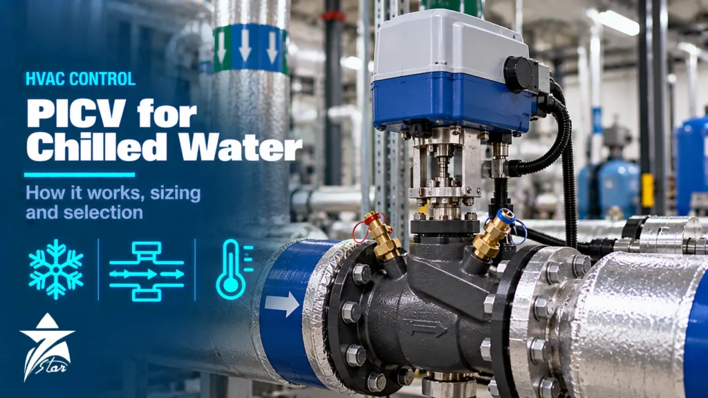
Chilled water systems in hot climates spend most of their running hours at part load, and that is exactly where conventional two-way control valves struggle. As other valves close, the differential pressure across the remaining ones rises, coils get more flow than they need, the chilled water return temperature falls and chillers and pumps work harder for the same cooling. A pressure independent control valve (PICV) solves this by keeping the flow through each terminal unit tied to the control signal, whatever the pressure in the system does. For contractors, consultants and facility teams looking for a PICV supplier in Oman, it also covers FCU valve kits and compares the PICV makes most often specified in Muscat and across the GCC. This guide explains how PICVs work, how they compare with conventional valve and balancing arrangements, how to size and select them, and what to check during installation and commissioning in GCC buildings and district cooling networks.
The Problem with Pressure-Dependent Valves
A normal two-way control valve passes a flow that depends on two things: its opening and the differential pressure across it. Designers size the valve for a design pressure drop, and balancing valves are set during commissioning to hold that condition at full load. As the building moves to part load and other valves throttle, pump head and pipe losses redistribute, and the pressure across an individual valve can rise significantly. The same 40 % opening now passes far more water than the controller expects.
- Overflow at coils: more water than needed passes through the coil with little extra cooling, so the return water temperature drops.
- Low delta-T syndrome: the chilled water temperature difference across the plant falls below design, so more pumping and more chillers are needed for the same load.
- Hunting: valve authority falls, the controller sees a valve that is too “strong” near closed, and room temperatures oscillate.
- Balancing effort: manual balancing is valid only at the condition it was set; it cannot follow changing loads.
How a Pressure Independent Control Valve Works
A PICV combines three functions in one body:
- Differential pressure regulator: a spring-loaded diaphragm or piston that maintains a constant differential pressure across the control part of the valve, absorbing pressure changes in the system.
- Flow limiting (presetting): an adjustable setting, usually a dial or ring, that sets the maximum flow the valve will pass when fully open.
- Control part: a plug or characterised element moved by an actuator according to the controller signal, typically 0–10 V or 2–10 V, or a simple on/off or floating signal on fan coil units.
Because the differential pressure across the control part is held constant, the flow at a given actuator position stays the same as system pressure changes. In practice this gives a valve authority close to 1, so the full actuator stroke is available for control. When the inlet differential pressure is below the valve’s minimum value, the regulator is fully open and the valve behaves like a normal pressure-dependent valve; above its maximum rating, the regulator can no longer compensate.
PICV vs Conventional Arrangements
| Arrangement | How flow is controlled | Strengths | Limitations |
|---|---|---|---|
| Two-way valve + manual balancing valve | Valve position; balancing set at design flow | Low device cost, simple | Flow varies with system pressure; low authority at part load; re-balancing needed after changes |
| Two-way valve + differential pressure control valve (DPCV) per branch | Branch differential pressure held constant | Good stability across a branch; fewer regulators | Terminal valves still interact within the branch; more commissioning steps |
| Pressure independent control valve | Flow per terminal held to the control signal | Authority near 1, no separate balancing, stable part-load control | Higher device cost; needs minimum differential pressure; dirt sensitive |
| Electronic or energy valve with flow sensor | Measured flow or energy closed-loop control | Measured data for monitoring and analytics | Higher cost, needs network and configuration |
Selecting and Sizing a PICV
PICVs are selected on design flow, not on Cv. The right valve is the smallest size whose flow range covers the design flow comfortably, usually with the design flow in the middle to upper part of the presetting range. Collect these data before selection:
- Design flow for each terminal unit (fan coil, AHU coil, heat exchanger), in l/s, l/h or m³/h.
- Minimum available differential pressure at each valve location at design flow, especially at the index (most remote) circuit.
- Maximum differential pressure the valve may see, normally at the nearest circuit at low load with pumps at full speed.
- Control signal type and actuator supply voltage (24 V AC/DC is common), fail position needs and any feedback signal.
- Characteristic: equal percentage is generally preferred for water coils, because coil heat output is non-linear with flow.
- Connection type and pressure rating: threaded for small fan coil valves, flanged for larger sizes, and the system’s PN rating.
- Water temperature range and fluid (plain water or glycol mixtures).
Minimum differential pressure is the critical figure. Manufacturer datasheets publish it, often in the range of about 15–35 kPa depending on size and presetting, and it usually rises as the presetting increases. Maximum working differential pressure is often around 400 kPa, though some models are rated higher. Pump head must provide the minimum differential pressure at the index valve plus pipe and coil losses, so selecting PICVs with lower minimum values can reduce pump energy.
The general principles of characteristic selection and valve authority are covered in our control valve selection and sizing guide; PICVs simplify the authority part of that work but not the need to know flows and pressures.
Actuators and Control Signals
- Thermoelectric (wax) actuators: on/off or slow modulating control on small fan coil valves; silent and low cost.
- Modulating electric actuators: 0–10 V or 2–10 V input with optional position feedback, for AHUs and larger coils.
- Communicating actuators: BACnet, Modbus or proprietary bus actuators that report position, and in some cases flow and temperature.
- Fail-safe actuators: spring or capacitor return to a defined position on power loss, used where freeze or overheating protection matters.
Match the actuator stroke and force to the valve body; manufacturers supply approved combinations. A mismatched actuator can leave the valve unable to close or limit the usable range.
Installation Good Practice
- Install PICVs on the return side of the coil unless the manufacturer states otherwise, with flow in the direction of the body arrow.
- Fit strainers upstream of terminal units and flush the system before installing or opening PICVs; debris in the regulator is the most common cause of failure.
- Provide pressure test points across the valve, either built in or as separate points, so the available differential pressure can be verified.
- Leave clear access for the presetting dial and the actuator.
- Use isolation valves on both sides of each terminal unit for maintenance.
- Protect actuators from condensation on chilled water lines; mount them above or beside the valve, not underneath, unless approved.
Commissioning and Verification
With PICVs, commissioning shifts from proportional balancing to verification. The basic steps are:
- Set the presetting on each valve to its design flow from the schedule.
- Run pumps under design conditions and measure differential pressure across the index valve with a manometer at the test points; confirm it is above the valve’s minimum.
- Adjust pump speed or the differential pressure setpoint until the index valve has its minimum plus a margin, which keeps pump energy as low as practical.
- Spot-check flows at selected terminals with the valve manufacturer’s method or an ultrasonic clamp-on meter.
- Stroke actuators from the building management system and confirm open, closed and mid positions.
Troubleshooting PICV Problems
- Room too warm, valve fully open: measure differential pressure across the valve; if it is below the minimum, the pump setpoint is too low or a strainer upstream is blocked.
- Coil flow too high at part load: check whether the presetting was changed or never set, and confirm the regulator is not jammed open by debris.
- Temperature hunting: review controller tuning and the actuator characteristic; a PICV removes pressure interaction but not poor loop tuning.
- Valve noisy: differential pressure may exceed the valve’s maximum rating at near circuits; lower the pump setpoint or add branch pressure control.
- Actuator does not move: check supply voltage, signal range (0–10 V versus 2–10 V) and whether the actuator is correctly coupled to the valve stem.
District Cooling and GCC Conditions
In Oman and across the GCC, cooling is the dominant building energy load, and many developments are served by district cooling plants that set limits on return water temperature and penalise low delta-T. PICVs at each terminal unit help maintain the design temperature difference across the building’s energy transfer station. High summer loads mean systems run long hours, so dirt management is important: maintain strainers, monitor water treatment and plan regular checks of differential pressure. Valves in plant rooms should also be rated for the system’s static pressure in high-rise buildings.
Common Mistakes with PICVs
- Selecting by pipe size rather than by design flow, so the valve operates at the bottom of its range.
- Not checking the minimum differential pressure at the index circuit, leaving remote coils starved.
- Leaving manual balancing valves fully closed or partly closed in series with PICVs, which adds unnecessary pressure drop.
- Installing without strainers or flushing, leading to blocked regulators.
- Running pumps at fixed full speed when PICVs would allow a lower differential pressure setpoint.
- Using a linear-characteristic actuator setting on a coil that needs equal-percentage control.
PICV Selection Checklist
- Design flow per terminal and presetting range confirmed
- Minimum and maximum differential pressure checked at index and near circuits
- Characteristic, actuator signal and fail position specified
- Size, connection and PN rating matched to the system
- Strainers, test points and isolation provided
- Flushing and water treatment plan in place before commissioning
- Pump differential pressure setpoint optimised after verification
FCU Valve Kits and PICV Piping Packages
On fan coil units and small air handling units, the PICV is rarely ordered on its own. Most projects in Oman specify a complete FCU valve kit (also called a valve package or hook-up kit), pre-assembled so that the installer connects two hoses and a cable instead of building the valve train on site. A typical kit contains:
- The PICV itself, sized by design flow, with its presetting already set or marked.
- An actuator matching the controls: on/off, floating (3-point) or modulating 0–10 V or 2–10 V, usually 24 V AC, with the required fail position.
- A Y-strainer with a blow-down valve upstream of the PICV, to protect the small internal passages from debris.
- Isolation ball valves on flow and return so the coil can be serviced without draining the riser.
- Pressure/temperature test points (P/T plugs) across the PICV to verify that the minimum differential pressure is available.
- Union connections and, where specified, braided stainless steel flexible hoses of a stated length to connect to the coil.
- Optional items: flushing bypass, drain valve, automatic air vent and pre-formed insulation shells for chilled water.
When you request a quotation for FCU valve kits, send the kit schedule with the design flow per unit, the pipe size, the actuator signal and supply voltage, the fail position, hose length and connection type, and whether insulation is required. Kits can be built around different PICV makes, so matching the brand named in the consultant’s specification is usually the first question to settle.
PICV Makes Compared
Most chilled water projects in Oman name one of a small group of PICV manufacturers. The table lists the ranges in our catalogue and the size ranges stated for them. Always confirm the final model against the manufacturer’s current datasheet, flow charts and minimum differential pressure.
| Make and range | Size range | Notes |
|---|---|---|
| Danfoss AB-QM | DN 15–250 | Widely specified mechanical PICV; NovoCon S digital actuator adds bus communication for DN 10–32. |
| IMI TA-Modulator and TA-COMPACT-P | DN 10–200 / DN 10–32 | Modulating PICV for coils and AHUs; compact version for fan coils. |
| Frese OPTIMA Compact and OPTIMA Compact Veriflow | DN 10–50 / DN 50–300 | Threaded terminal-unit valve and flanged version for large coils and plant. |
| Siemens VPI46 and VPF44 / VPF54 | DN 15–50 / DN 50–200 | Threaded combi valve and flanged PICV, often paired with Siemens actuators and controls. |
| Belimo EPIV and Belimo Energy Valve | DN 65–150 / DN 15–50 | Electronic pressure independent valves with flow measurement; the Energy Valve adds thermal energy metering. |
| Belimo PIQCV piping package | DN 15–20 | Ready-made piping package with a PI zone valve for fan coils. |
Pressure Independent Control Valves We Supply
These examples cover PICVs, actuators and FCU piping packages from several makers.
For PICVs or complete FCU valve kits, send the valve schedule with design flow, pipe size, actuator signal and available differential pressure through our quote request form.
Buying PICVs in Oman Through Seven Star LLC
Seven Star LLC supplies pressure independent control valves, valve actuators and HVAC components on request for buildings, district cooling and industrial cooling systems in Oman and the GCC. As an independent PICV supplier in Oman, we quote the make named in your specification or offer comparable alternatives. We help with selection and with cross-checking flow ranges, actuator combinations and part numbers between manufacturers; availability and lead time are confirmed at quotation. For process applications beyond HVAC, see our range of control valves.
Send us your valve schedule with design flows and differential pressures, or the nameplate of the existing PICV and actuator, and we will prepare a matching quotation.
Frequently asked questions
What is a pressure independent control valve?
A PICV combines a differential pressure regulator, a flow-limiting presetting and a control valve in one body. The regulator keeps a constant pressure across the control part, so the flow at any actuator position stays the same even when system pressure changes. This gives stable control and removes the need for separate balancing valves at each terminal.
How do I size a PICV?
Size by design flow, not by pipe size or Cv. Choose the smallest valve whose flow range covers the design flow, then confirm that the available differential pressure at the valve exceeds its minimum requirement. The manufacturer's flow and differential pressure charts govern the final choice.
What is the minimum differential pressure for a PICV?
It depends on the model, size and presetting, and is shown on the manufacturer's datasheet. Typical published values are in the range of roughly 15–35 kPa. Below the minimum, the valve can no longer control flow independently of pressure.
Do I still need balancing valves with PICVs?
Generally not at each terminal unit, because each PICV limits its own flow. Some designs still use branch-level devices for isolation, flow measurement or to manage very high differential pressures. Avoid leaving extra throttling valves in series that add unnecessary pressure drop.
Why do PICVs help with low delta-T syndrome?
Low delta-T often comes from coils receiving more water than needed at part load. PICVs keep flow in line with the control signal, so coils do not overflow and the return water temperature stays closer to design. This reduces pumping and chiller staging for the same load.
Where should a PICV be installed?
Usually on the return side of the coil, with the flow direction matching the arrow on the body, a strainer upstream and pressure test points available. Always follow the manufacturer's installation instructions, as some designs allow supply-side installation.
Where can I buy PICVs and FCU valve kits in Oman?
Seven Star LLC is an independent supplier in Oman that quotes PICVs, actuators and FCU valve kits from makers such as Danfoss, IMI TA, Frese, Siemens and Belimo. Send the valve schedule with design flows, pipe sizes, actuator signal and fail position through the quote request form or to [email protected], and availability and lead time are confirmed at quotation.
Was this guide helpful?One click helps us write better guides for engineers.
Thank you! Glad it helped. Need this equipment for your project? Request a quotation
Thank you. We will use this to improve the guide.