What the BIM-M12E-AP4X-H1141 does
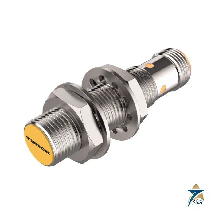
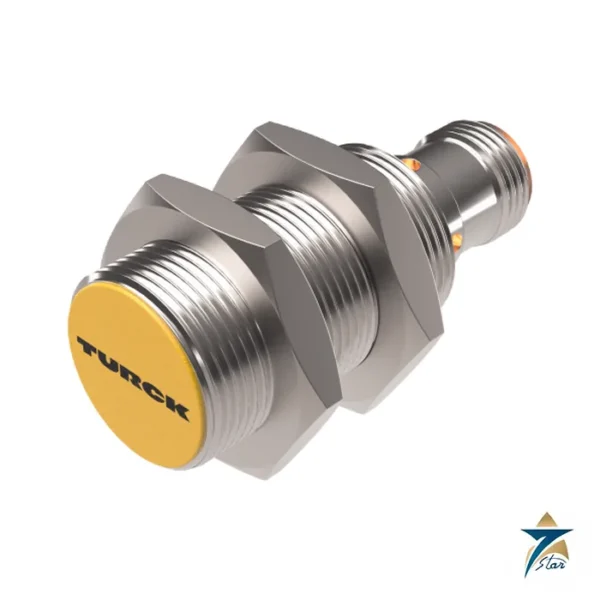
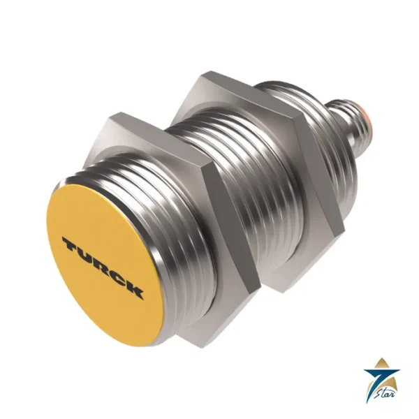
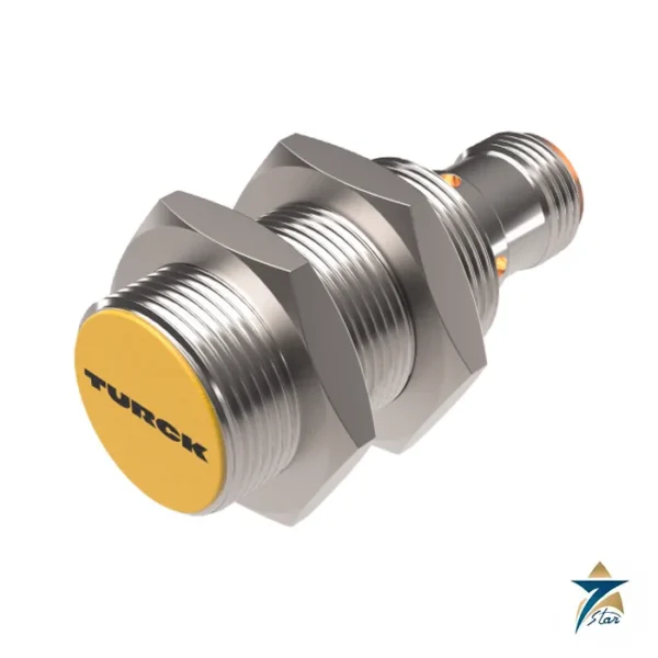
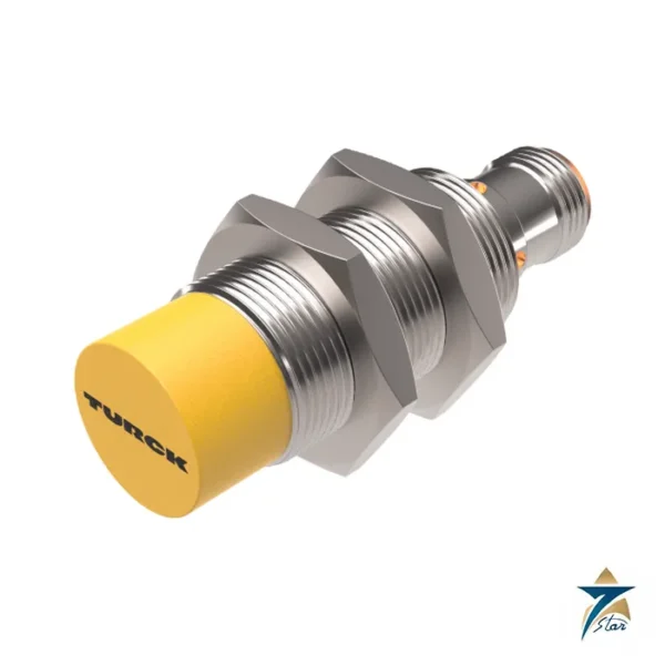
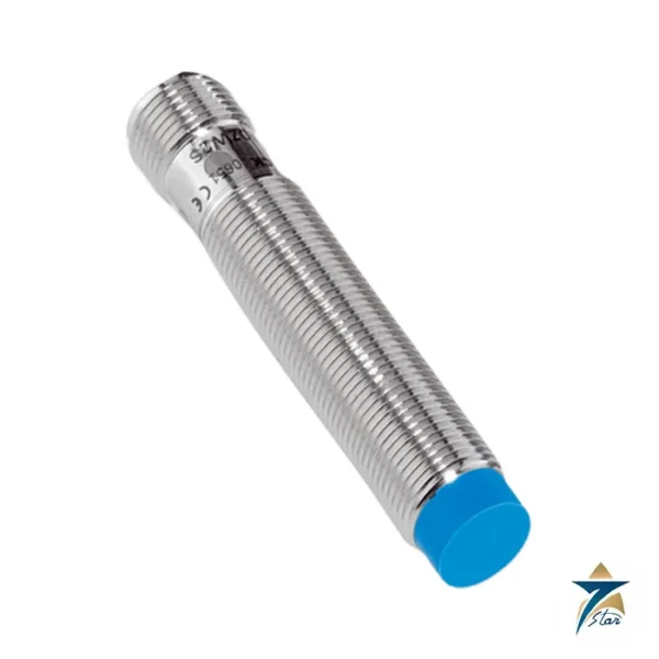
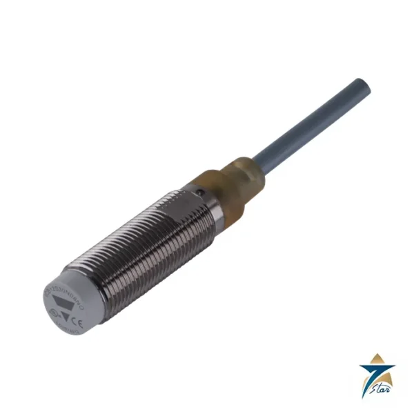
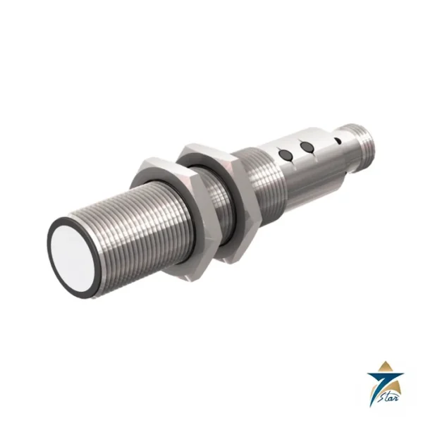
BIM-M12E-AP4X-H1141 is a magnetic-inductive proximity sensor in an M12 x 1 chrome-plated brass barrel, rated for 90 mm operating distance when used with the DMR31-15-5 magnet named in the datasheet, with a 3-wire PNP normally-open output.
Headline features from the datasheet: DC 3‐wire, 10…65 VDC; Male connector, M12 x 1; Threaded barrel, M12 x 1; Chrome-plated brass; Rated operating distance 90 mm with; NO contact, PNP output.
Technical specifications
| Parameter |
Specification |
| Type |
BIM-M12E-AP4X-H1141 |
| Ident number |
1579913 |
| Rated switching distance |
90 mm |
| Repeat accuracy |
≤ 0.3 % of full scale |
| Temperature drift |
≤ ±15 % |
| Hysteresis |
1…10 % |
| Operating voltage UB |
10…65 VDC |
| Ripple Uss |
≤ 10 % UBmax |
| DC rated operating current Ie |
≤ 200 mA |
| No-load current |
≤ 15 mA |
| Residual current |
≤ 0.1 mA |
| Isolation test voltage |
0.5 kV |
| Short-circuit protection |
yes/Cyclic |
| Voltage drop at Ie |
≤ 1.8 V |
| Wire break/reverse polarity protection |
yes/Complete |
| Output function |
3-wire, NO contact, PNP |
| Switching frequency |
1 kHz |
| Design |
Threaded barrel, M12 x 1 |
| Housing material |
Metal, CuZn, Chrome-plated |
| Active area material |
Plastic, PBT-GF30 |
| Max. tightening torque of housing nut |
10 Nm |
| Electrical connection |
Connector, M12 × 1 |
| Ambient temperature |
-25…+70 °C |
| Vibration resistance |
55 Hz (1 mm) |
| Shock resistance |
30 g (11 ms) |
| Protection class |
IP67 |
| MTTF |
2283 years acc. to SN 29500 (Ed. 99) 40 |
| Switching state |
LED, Yellow |
Where it fits and how it behaves
Instead of sensing metal, this sensor reacts to a permanent magnet, so it can read through non-ferromagnetic materials such as wood, plastics or stainless-steel covers as described in the datasheet. A 90 mm reach with the specified magnet is very large for an M12 body, which makes it handy for detecting float, piston or door positions through a wall. Always verify the magnet type, since the rated distance applies to the DMR31-15-5 magnet only. Because the 90 mm figure is tied to a specific magnet, the same sensor with a different magnet will switch at a different distance, and the magnet is a separate item. The datasheet lists a 10 Nm tightening torque for the housing nut, a 1 kHz switching frequency and an MTTF of 2283 years at 40 C according to SN 29500, which is a calculated reliability figure and not a service-life promise.
Installation hint: confirm which magnet is used, keep other magnets and ferromagnetic masses away from the sensing area, and check the switching point in the installed position, because the real distance depends on magnet orientation and the wall material between magnet and sensor.
Type code, ident number and checks
Ident number 1579913 identifies this exact variant. The datasheet gives the output as 3-wire, NO contact, PNP and the connection as Connector, M12 × 1; other housing, output and cable versions carry different type codes and ident numbers.
A short checklist before you order: the ambient temperature range, the connector or cable length, the magnet or cylinder type the rated distance refers to, and the output type and supply voltage. Specifications here are restated from the official datasheet and should be matched against the current maker revision.
Mounting the sensor and its magnet
Fix the sensor through a clearance hole or bracket using its two housing nuts, and do not exceed the tightening torque given in the specification table, since overtightening can damage the barrel thread. Align the sensor axis with the path of the magnet, and remember that the sensing face is the plastic active area at the front of the barrel. Where the magnet travels behind a wall, measure the actual gap between magnet and sensing face including the wall thickness, rather than relying on the nominal distance alone.
The magnet should be fixed so that it cannot rotate or shift in service, because a change in orientation alters the switching point. Avoid mounting the magnet on or next to ferromagnetic steel without first testing the arrangement, as nearby iron can bend the field and shorten the effective range. Keep cables and other sensors that contain magnets clear of the sensing zone.
Wiring and commissioning
Use a matching M12 connector cable and connect the supply and output conductors according to the wiring diagram in the Turck datasheet, with the PNP output going to a sourcing-compatible input on the PLC or relay. Confirm the supply voltage at the connector is within the stated range before final testing. During commissioning, move the magnet slowly towards and away from the sensor to find the switch-on and switch-off points, and confirm that both points sit comfortably inside the travel of the machine part, allowing for the hysteresis listed above.
Record the confirmed switching position in the commissioning notes. If the application involves a float or piston, test at both ends of the expected travel and under normal operating vibration, so that the output does not chatter at the edge of the range.
Selection checks for the application
- Confirm that the wall between magnet and sensor is non-ferromagnetic and note its thickness.
- Check whether the machine already uses a magnet, and if so whether it matches the one the rated distance refers to.
- Compare the required switching rate with the switching frequency in the table.
- Confirm that a 3-wire PNP normally-open output suits the controller input card.
Operation in Oman and GCC conditions
The sensor is rated IP67 with an ambient range of -25 to +70 °C, but surface temperatures in direct summer sun in the Gulf can climb well above air temperature, particularly on dark steel frames. Where possible, mount the sensor in shade or behind a sun shield and check the actual surface temperature at the mounting point. Fine dust does not affect magnetic sensing in the way it affects optical sensors, yet heavy build-up of iron-bearing dust or metal swarf on the sensing face can still influence the field and should be cleaned off during routine maintenance.
On coastal and humid sites, pay attention to the connector: make sure the cable coupling is fully tightened so the seal works, and inspect it for corrosion or moisture ingress during plant inspections. A simple periodic check of the switching point with the magnet confirms that nothing in the installation has shifted.
Documents and quotation
Download the Turck datasheet for BIM-M12E-AP4X-H1141 and compare it with your drawing or loop data. Pricing and lead time are not shown on the page; Seven Star LLC, an independent supplier based in Muscat, quotes them on request. Quote the full type code BIM-M12E-AP4X-H1141 so the correct variant is offered. More related items are listed under Inductive Proximity Sensors.






Reviews
There are no reviews yet.