RT 14 thermostat for cold rooms, air heaters and frost protection from -5 to 30 C
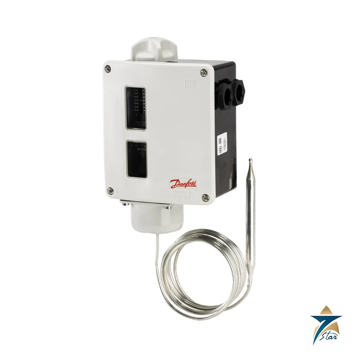
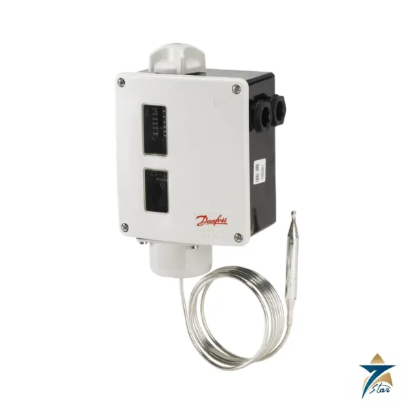
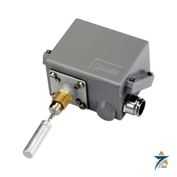
The 017-509966 is a Danfoss RT 14 thermostat, a single-pole change-over temperature switch whose contact position depends on the temperature of the sensor and the scale setting. A 9.5 x 110 mm remote bulb is connected by a 2 m capillary tube, so the control head can sit in a panel or on a wall while the bulb measures air in a duct, a cold room or a tank. The adsorption charge gives a wide adjustable differential, which is useful where short cycling of heaters, fans or compressors has to be avoided.
Within the RT series, thermostats are offered with room sensors, duct sensors and capillary tube sensors for general industrial and marine use. The series data sheet lists high accuracy, high repeatability, long life and a SIL 2 capability per IEC 61508.
Technical specifications
| Parameter |
Specification |
| Danfoss code number |
017-509966 |
| Type |
RT14 |
| Function |
Thermostat with remote bulb, automatic reset |
| Temperature range |
-5 to 30 C |
| Differential (adjustable) |
2-8 C at minimum setting; 2-10 C at maximum setting |
| Contact system |
SPDT |
| Contact rating |
AC15=3 A, 400 V; AC1=10 A, 400 V; AC3=4 A, 400 V; DC13=12 W, 220 V; LR=28 A, 400 V |
| Enclosure |
IP66 |
| Sensor |
Remote bulb 9.5 x 110 mm, adsorption charge |
| Capillary tube length |
2000 mm |
| Min. sensor pocket length |
112 mm |
| Max. sensor temperature |
150 C |
| Ambient temperature |
-50 to 70 C |
| Cable entry |
2 x Pg 13.5, screwed |
| Approvals as listed |
CCC; CE; CMIM; EAC; GL; LVD; NKK; RoHS; RoHS China; TYSK; UA |
| Net weight |
0.862 kg |
| EAN |
5702428519250 |
Using the bulb correctly
The range of -5 to 30 C is aimed at cooling and ventilation control and at frost monitoring of air systems. Keep the bulb at least as warm or cold as the point you want to control and let it see moving air or liquid; a bulb in a dead pocket reacts slowly and the differential grows. The maximum sensor temperature of 150 C means the bulb may be exposed to short excursions far above the scale end without damage, but it should not be left there.
The capillary must not be kinked, and any excess length should be coiled in a loose bundle away from heat. Where the bulb is placed in a pocket, the pocket must be at least 112 mm long so the sensing part is fully immersed.
Setting and wiring
Set the cut-in on the large scale and adjust the differential spindle between 2 and 10 K depending on the position on the scale. The change-over contact allows both heating and cooling logic. Cable enters via the two Pg 13.5 glands; the installation guide for the RT 2, RT 7, RT 8, RT 12, RT 14 and RT 15 thermostats gives the terminal layout.
Confirm the ambient window, the sensor medium and the load current before ordering, because the same RT 14 type exists with other capillary lengths such as 3, 5, 8 and 10 m under different code numbers. Seven Star LLC is an independent supplier in Muscat.
Keep the data sheet, a photograph of the nameplate and the order code 017-509966 together in the plant record. The same family contains many similar codes that differ only in range, connection or options, and a clear record saves time when a spare is needed during a shutdown.
Choosing where to mount the RT 14 head and bulb
With a 2 m capillary, the control head and the remote bulb have to be planned as a pair. Pick the bulb position first, at the point whose temperature actually matters to the process, such as the coil outlet of an air heater, the return air of a cold room or a section of duct at risk of frost. Then find a mounting point for the head within reach of the capillary that is easy to access for setting and inspection, and that keeps the cable entries pointing in a sensible direction for the field wiring.
Avoid placing the bulb close to door openings, defrost heaters, lamps or direct sunlight, because these local effects can make the thermostat switch on conditions that do not represent the space or medium being controlled. Secure the capillary along its route with suitable clips so that it cannot vibrate against sharp edges.
Matching the contact to the load
The SPDT contact ratings in the table differ by utilisation category, so check whether the thermostat will switch a contactor coil, a resistive heater or a motor load directly. In many installations the RT 14 drives a contactor or a control relay rather than the full load, which keeps the contact well inside its rating and simplifies replacement.
Commissioning and checking the setpoint
After wiring, set the range scale to the required value and the differential to the widest setting the process can accept; a wider differential reduces the number of switching cycles. Then compare the switching point with an independent reference thermometer placed beside the bulb. Small adjustments are normal at commissioning, because the actual switching point depends on how quickly the medium around the bulb changes temperature.
Record the final range and differential settings on the panel drawing or a tag near the thermostat. If the unit forms part of a frost protection or safety-related function, the loop should be checked in line with the plant’s own procedures, using the series information on SIL capability only as one input to that assessment.
Operating in Oman and Gulf conditions
The IP66 enclosure and the wide ambient range listed in the specification table suit plant rooms, rooftops and marine areas, but heat and sun still need consideration in the Gulf. A head mounted on a sun-exposed wall can become much hotter than the surrounding air, so choose a shaded location where possible. Make sure the cable glands are correctly tightened and that unused entries are sealed, as dust and humid coastal air will find any gap.
In air-conditioning and ventilation systems in Oman, the -5 to 30 C range is often used for cold store, coil and supply air monitoring. Check that the expected operating temperature sits comfortably inside the scale rather than at either end.
Periodic inspection
During routine maintenance, inspect the capillary for kinks, crushing or abrasion, confirm that the bulb is still firmly fixed in its pocket or bracket, and check the setpoint against a reference thermometer. Look at terminal tightness and cable condition at the glands, and replace a thermostat whose capillary has been damaged rather than attempting a repair.
Documents and quotation
The attached Danfoss RT thermostat data sheet AI555726775232 gives the range tables and dimensions. Find related controls in temperature instrumentation. Request a price for 017-509966 with the quantity needed.














Reviews
There are no reviews yet.