
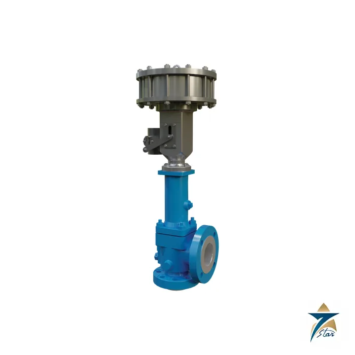
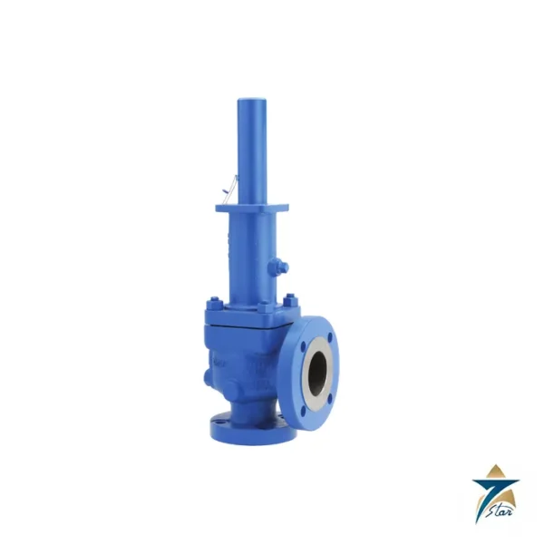
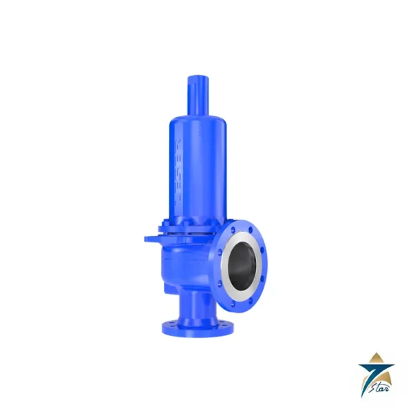
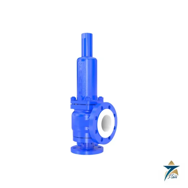
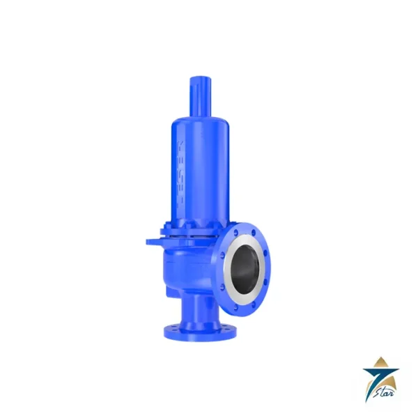
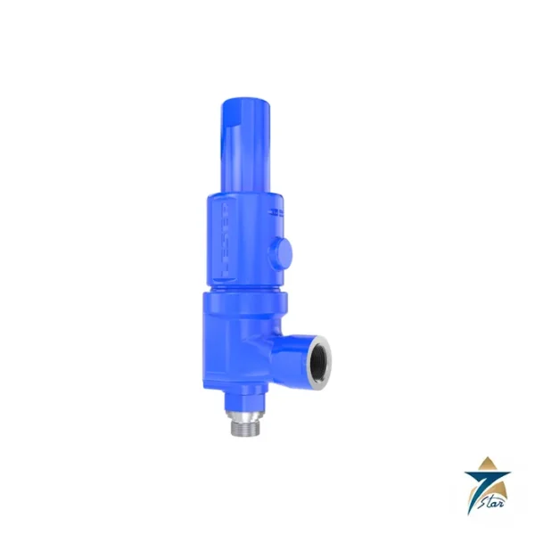
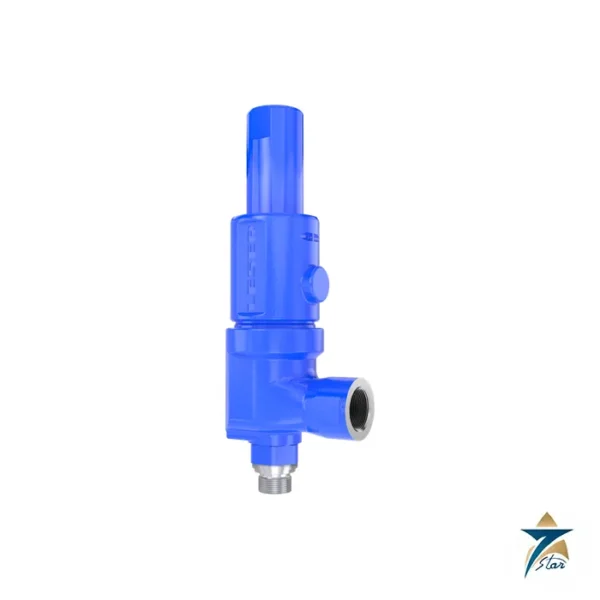
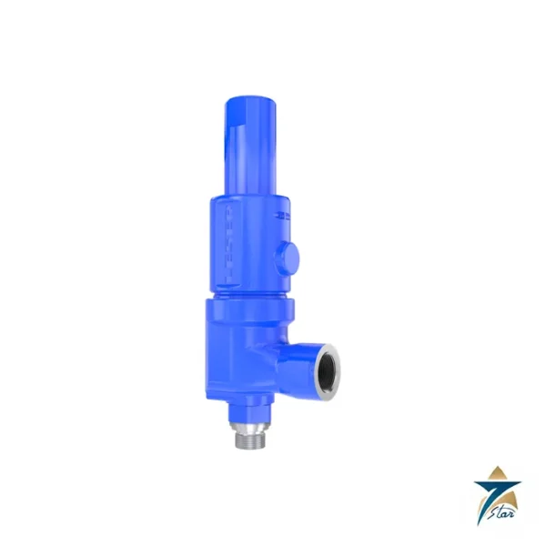
The Crosby JBS-E SIL 3 pneumatic actuated relief valve is an instrumented overpressure solution that combines a standard Crosby JBS-E balanced bellows relief valve with a pneumatic piston actuator. Emerson positions it as an emergency pressure relief solution capable of remote actuation, so that the valve can be opened on demand as part of a Safety Instrumented System or a Controlled Safety Pressure Relief System, while it still provides conventional spring-loaded protection if an overpressure event occurs without any signal from the logic solver.
For operators the Crosby JBS-E SIL 3 means a single device can serve as both the last line of mechanical defence and an active depressurisation element. The data sheet notes that the approach can reduce the need for dedicated emergency blowdown valves, the associated piping and the added construction cost. Seven Star LLC supplies the Crosby JBS-E SIL 3 actuated package to oil, gas and petrochemical projects in Oman and the GCC, working with EPC contractors and plant safety teams in Muscat to align valve size, actuator sizing and instrumentation with the project safety requirement specification.
A Safety Instrumented System reads process signals from sensors, uses a logic solver to decide whether a safety condition exists, and drives a final element to take the process to a safe state. In this application the final element is the relief valve. During a fire, a runaway reaction or another upset, the sensors send a signal to the logic controller, which is not included with the valve, and the controller issues an open command to the pneumatic actuator. The actuator lifts the valve elements and the process depressurises through the relief path.
Once the system has reached a safe operating state, the Crosby JBS-E SIL 3 actuator is depressurised and the relief valve returns to its normal fail-closed condition. The actuator is a controlled piston linear design that loads the valve spindle directly in line, without the levers or cams of a conventional lifting arrangement, and it is capable of lifting the relief valve fully independent of the process pressure at the valve inlet. Because the underlying valve of the Crosby JBS-E SIL 3 is a standard Crosby JBS-E direct spring valve, the spring-loaded function continues to operate as normal protection against overpressure whether or not the actuator is energised.
The Crosby JBS-E SIL 3 actuator operates on standard instrument air with a maximum allowable operating pressure of 120 psig (8.3 bar) and a minimum recommended pressure of 13 psig (0.9 bar). The standard pressure connection is 1/2 NPT internal, and the standard construction with Viton O-rings has operating temperature limits of -15 to 400 degF (-26 to 204 degC), with other materials available on request. Actuators are sized according to the valve selection, and the construction uses stainless steel materials for rugged service in outdoor oil and gas environments.
The data sheet illustrates three typical installation types for the package. The first uses a limit switch and a solenoid valve, with the logic solver driving a 24 V DC digital output to the solenoid and reading open and closed limit switches. The second replaces the limit switches with a position transmitter that returns a 4-20 mA signal. The third uses a valve positioner or digital valve controller, such as a Fisher FIELDVUE DVC 6200, for analog control and feedback. Monitoring options include TopWorx GO switches and Fisher position transmitters, and the logic solver, pressure transmitters and hazardous area hardware are provided according to project requirements.
The Crosby JBS-E SIL 3 packages remote actuation and instrumented diagnostics into a recognised relief valve platform:
The Crosby JBS-E SIL 3 is relevant to process units where a controlled depressurisation is part of the safety design: hydrocracking and hydrotreating reactors, gas processing trains, high pressure separators, pressure vessels with fire exposure scenarios and chemical reactors prone to runaway. In the refineries and petrochemical complexes of Sohar and Duqm and in gas facilities across the Sultanate, an actuated relief valve can be integrated with the unit emergency shutdown logic so that depressurisation starts when the safety function demands it, instead of waiting for pressure to reach the spring set point.
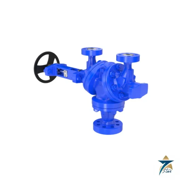
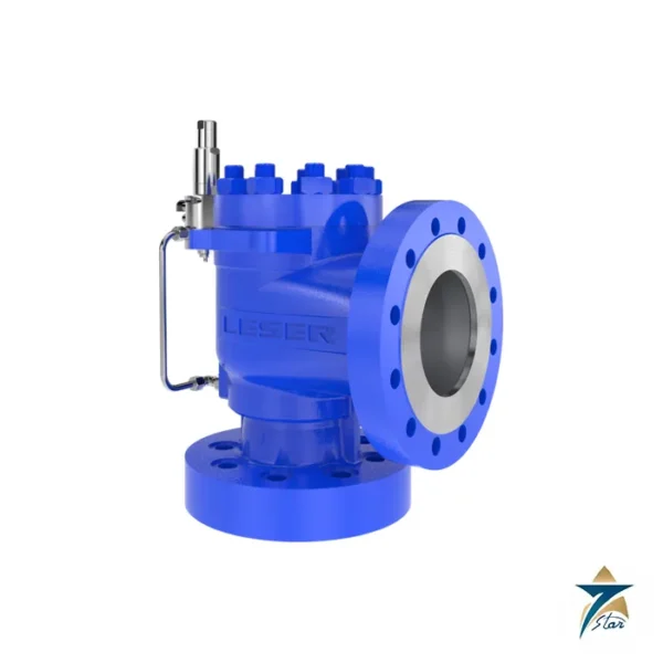
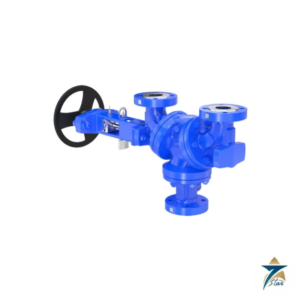
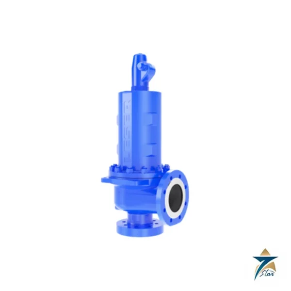
Typical interfaces for this actuated package are the plant ESD or fire and gas system and the control valve and instrument supplier for the actuator accessories. Seven Star LLC can quote the package together with compatible position feedback, and teams selecting a relief concept can compare it with a conventional design such as the LESER Type 526 API 526 flanged safety relief valve, with isolation arrangements like the LESER Type 310 change-over valve, or with pilot-operated solutions such as the Anderson Greenwood Series 90/9000 pressure relief valve.
The table summarises the published Crosby JBS-E SIL 3 data; actuator sizing and instrumentation are defined per project.
| Parameter | Specification |
|---|---|
| Model | Crosby JBS-E SIL 3 capable pneumatic actuated relief valve |
| Base valve | Crosby JBS-E direct spring balanced bellows relief valve |
| Safety capability | SIL 3 capable per IEC 61508 |
| Sizes (ANSI) | 1 D 2 to 12 W 16 inch |
| Sizes (EN type) | 25 D 50 to 200 T 250 |
| Orifice area | 0.110 to 60.75 in2 (71 to 39,193 mm2) |
| Inlet ratings | ANSI 150, 300, 600, 900, 1500, 2500; EN PN 10, 16, 25, 40 |
| Valve temperature range | -450 to +1000 degF (-268 to +538 degC) |
| Set pressure | 25 to 6000 psig (1.75 to 413.79 barg) |
| Actuator supply pressure | 13 psig minimum recommended; 120 psig (8.3 bar) maximum |
| Actuator temperature limits | -15 to 400 degF (-26 to 204 degC) with Viton O-rings |
| Air connection | 1/2 NPT internal (standard) |
| Position monitoring | TopWorx GO switches, Fisher position transmitters, DVC 6200 option |
To request a quotation for the Crosby JBS-E SIL 3 actuated relief valve, send Seven Star LLC your safety requirement specification, relieving case, set pressure, inlet and outlet flange class, instrument air conditions and the preferred position feedback method. Our Muscat team will review the Crosby JBS-E SIL 3 requirements against the attached Crosby data sheet and the J-Series catalog for the base valve, and confirm the package, availability and lead time for projects in Oman and the GCC.
Browse Crosby products by category: Safety Relief Valves.
Choose the option that best fits your needs to get the fastest response from our team.
Automatically fill the RFQ form with this product's details for a faster process.
Manually enter multiple part numbers, specific brands, or custom requirements.











Reviews
There are no reviews yet.