- Automation & ControlView all 1,657 products
- AC Drives
- Industrial Communications
- PLC & I/O Cards
- Vibration Monitoring
- Automation Accessories
- Controllers & Data Acquisition
- CCTV & Security
- Safety Switches & Guard Locking
- Encoders
- Industrial Computers
- Servo Drives
- Isolator & Barrier
- Motor Soft Starters
- HMI Displays
- Pneumatic Cylinders
- Automation Software
- Machine Vision
- Robotics
















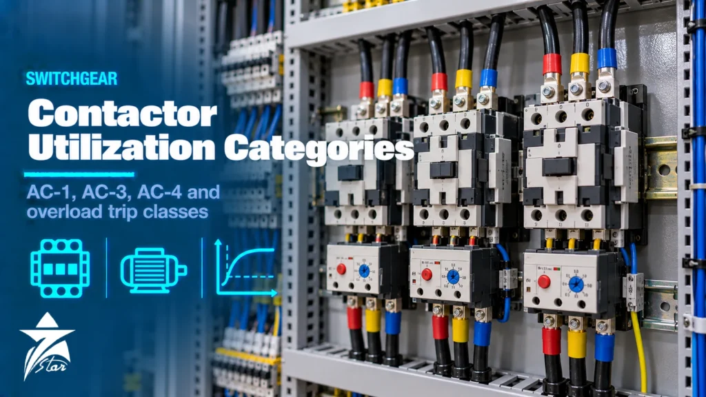
Two contactors with the same frame size and the same catalogue current can behave very differently in service: one runs a pump for years, the other welds its contacts within months on a crane hoist. The difference is almost always the duty, and that is what contactor utilization categories in IEC 60947-4-1 describe. This guide explains AC-1, AC-3, AC-3e and AC-4 in practical terms, how to size contactors for motors, heaters and capacitors, how thermal and electronic overload relays and trip classes work, what Type 1 and Type 2 coordination really mean, and the mistakes that cause chattering, welding and nuisance trips.
How a Contactor and Overload Relay Work Together
A contactor is an electrically operated switch designed for frequent operation. A coil energises a magnet that closes the main contacts; when the coil is de-energised, springs open them and arc chutes extinguish the arc. A contactor is not a protective device. It makes and breaks normal operating currents, including motor starting current, but it is not designed to interrupt short-circuit currents.
The overload relay, mounted directly on the contactor or separately, protects the motor against sustained overcurrent, such as a jammed pump or a lost phase. It does not switch the main circuit itself; it opens an auxiliary contact in the coil circuit, which drops out the contactor. Short-circuit protection comes from a third device upstream: fuses, a motor circuit breaker or an MCCB. The three together form a motor starter, and IEC 60947-4-1 is the product standard that defines how they are rated and tested.
Contactor Utilization Categories in IEC 60947-4-1
A contactor’s rated operational current (Ie) is meaningless without its utilization category and voltage. The category defines the current and power factor the contactor must make and break in normal use, which drives contact erosion and electrical life.
| Category | Typical load | Switching duty | What it means in practice |
|---|---|---|---|
| AC-1 | Non-inductive or slightly inductive loads, resistance heaters | Makes and breaks roughly rated current at high power factor | Easiest duty; the AC-1 rating of a frame is much higher than its AC-3 rating |
| AC-2 | Slip-ring (wound-rotor) motors | Starting and switching off | Mostly legacy installations |
| AC-3 | Squirrel-cage motors | Starting, and switching off while running | Makes the starting current, breaks roughly the running current; the standard motor rating |
| AC-3e | Squirrel-cage motors, including high-efficiency designs | As AC-3, with making conditions that account for the higher inrush peaks of high-efficiency motors | Added in the 2018 edition; check it when applying IE3 and IE4 motors |
| AC-4 | Squirrel-cage motors | Starting, plugging (reverse braking) and inching (jogging) | Breaks the starting current; severe arc erosion and much shorter contact life |
| AC-5a | Switching of electric discharge lamp controls | Lamp loads with inrush | Lighting contactors |
| AC-6b | Switching of capacitor banks | Very high inrush peaks at energisation | Use dedicated capacitor-duty contactors or apply the manufacturer’s derating |
DC loads have their own categories, such as DC-1 for resistive loads and DC-3 and DC-5 for shunt and series motors. DC arcs are harder to extinguish because there is no current zero, so DC ratings are often achieved by connecting poles in series.
Why AC-3 and AC-4 Contactor Utilization Categories Are So Different
When a squirrel-cage motor starts direct-on-line, it draws a locked-rotor current that is typically several times its rated current, commonly in the region of six to eight times. In AC-3 duty the contactor must make that current but only breaks the running current once the motor has accelerated, so the arc at opening is modest.
In AC-4 duty, the contactor opens while the motor is still at or near standstill: during inching, or when reversing the motor before it stops. It must then break the full starting current. The arc energy is far higher, the contacts erode quickly and electrical life falls by a large factor. Manufacturers publish separate AC-4 ratings and life curves for this reason. Applying an AC-3 rated contactor to a crane, hoist or conveyor that is jogged frequently is one of the most common causes of premature contact failure.
The practical rules are simple:
- For motors started and stopped normally, select by AC-3 (or AC-3e) rating at the supply voltage, using the motor’s rated current or power.
- For inching, plugging or frequent reversing, use the manufacturer’s AC-4 rating or mixed AC-3/AC-4 life curves, which usually means a larger frame.
- For heaters and other resistive loads, AC-1 applies, allowing a smaller frame than the same current would need in AC-3.
- For capacitor banks, use contactors designed for capacitor switching, often fitted with pre-charge resistors to limit inrush.
Mechanical vs Electrical Life
Mechanical life is the number of no-load operations before the mechanism wears out and is usually in the millions. Electrical life is the number of operations under load before the contacts are worn, and depends heavily on category, current and voltage. A contactor that switches a small fraction of its AC-3 rating may last for a very large number of operations, while the same contactor at full AC-4 duty may need contact replacement much sooner. For high-cycle applications such as packaging machines or compressors with frequent loading and unloading, check the manufacturer’s electrical life curve at your actual current rather than relying on the catalogue headline.
Overload Relays: Thermal vs Electronic
Thermal (bimetal) overload relays
A heater element in each phase warms a bimetal strip; sustained overcurrent bends the strips until a trip mechanism operates. Most are ambient-temperature compensated within a stated range and include differential (phase-loss) sensitivity, which trips faster when one phase carries much less current than the others. They are simple, low cost and do not need an auxiliary supply, but they have a narrow adjustment range and their characteristics are affected by mounting position and nearby heat sources.
Electronic overload relays
Current transformers measure phase currents and a microcontroller models motor heating. Benefits include wide adjustment ranges (fewer variants to stock), selectable trip class, accurate phase-loss and imbalance detection, ground-fault detection on some models, and communication on higher-end devices. Many are self-powered from the measured current. In hot panels, electronic relays are less sensitive to ambient temperature than bimetal designs, although their own electronics still have temperature limits.
Trip classes
The trip class defines the maximum tripping time from cold at 7.2 times the current setting. Class 10A and Class 10 trip within 10 seconds, Class 20 within 20 seconds and Class 30 within 30 seconds. Most standard motors on pumps and fans are protected with Class 10. Heavy-inertia loads such as large fans, centrifuges, crushers and loaded conveyors may need Class 20 or 30 so the relay does not trip during a long acceleration, provided the motor manufacturer confirms that the motor can withstand the longer stall time.
Setting the Overload Relay Correctly
- Set the relay to the motor’s rated current from the nameplate at the actual supply voltage and connection, not to the contactor rating or a rounded-up figure.
- For star-delta starters with the relay in the motor phase circuit, set it to about 0.58 times the motor rated current (1/√3), because it carries phase current rather than line current.
- If the motor has been derated for high ambient temperature or altitude, set the relay to the derated current rather than the 40 °C nameplate value.
- Choose the trip class from the measured or calculated run-up time, not by default.
- Decide between manual and automatic reset. Automatic reset can restart a motor unexpectedly on a two-wire control circuit and is usually avoided where this creates a hazard.
Motors supplied from variable speed drives are normally protected by the drive’s own electronic motor overload function; a separate thermal relay downstream of a drive can misread the non-sinusoidal current. Our guide to VFD selection for hot climates covers drive-side motor protection.
Type 1 and Type 2 Coordination
Coordination describes how the starter behaves when the short-circuit protective device (SCPD) clears a fault on the motor circuit. IEC 60947-4-1 defines two levels, and manufacturers publish tested combinations of SCPD, contactor and overload relay for each, at stated prospective short-circuit currents and voltages.
- Type 1: under short-circuit conditions the starter must not cause danger to people or the installation, but it may be unfit for further service without repair or replacement of parts. Acceptable where downtime after a fault is tolerable.
- Type 2: the starter must remain suitable for further use after the fault. Light welding of contacts is recognised as a risk, provided they can be separated easily and the manufacturer gives maintenance instructions. Required for process plants, critical pumps and continuous operations where a starter must be back in service quickly.
Coordination is only valid for the exact combination tested. Changing the fuse type, the MCCB model or the contactor size, even to a nominally larger one, can invalidate it. Always take the combination from the manufacturer’s coordination tables for the prospective fault current at the switchboard. For upstream protective devices, see our circuit breakers category.
Coils, Control Voltage and Hot-Panel Effects
- Coil voltage and type: AC coils, DC coils and electronic wide-range coils exist. Electronic coils tolerate voltage variation better and draw less holding power, which reduces panel heat.
- Voltage dips: AC contactors drop out below a certain coil voltage. On weak supplies or during large motor starts, this can cause chatter or unwanted stops. Ride-through modules or DC control supplies help.
- Coil suppression: RC modules, varistors or diodes limit switching surges that disturb PLC outputs. Diodes on DC coils noticeably lengthen drop-out time, which matters for safety and reversing interlocks.
- Ambient temperature: catalogue ratings are given at a stated ambient around the device. In GCC panels with internal temperatures well above that figure, apply the manufacturer’s derating for current and check coil operating limits.
- Reversing and star-delta: use mechanical and electrical interlocks between contactors that must never close together. In star-delta starters, line and delta contactors carry about 0.58 times and the star contactor about one-third of the motor rated current.
Troubleshooting Common Failures
| Symptom | Likely causes | Checks |
|---|---|---|
| Contactor chatters or hums | Low coil voltage, dirt or rust on AC magnet faces, broken shading ring | Measure coil voltage during motor start; clean or replace magnet assembly |
| Contacts welded | AC-4 duty on an AC-3 contactor, undersized for inrush, short circuit without Type 2 coordination | Review duty cycle and coordination tables; upsize frame |
| Burnt or pitted contacts | Frequent inching, loose terminals, excessive switching rate | Check terminal torque and operations per hour against rating |
| Overload trips during start | Trip class too low for load inertia, relay set below motor current | Measure start time and current; review class and setting |
| Overload trips in summer | High panel temperature affecting bimetal, motor overloaded by hot air or dirty cooling | Measure panel internal temperature and motor current |
| Motor runs hot without trip | Relay set too high, single phasing on a relay without phase-loss sensitivity | Verify setting against nameplate; test phase-loss function |
Selection Checklist
- Load type and utilization category (AC-1, AC-3, AC-3e, AC-4, capacitor or lamp duty).
- Motor power, rated current, voltage and starting method (DOL, star-delta, reversing).
- Operations per hour and expected inching or plugging.
- Coil voltage and type (AC, DC or electronic wide-range) and auxiliary contact requirements.
- Overload relay type, setting range and trip class; manual or automatic reset.
- Prospective short-circuit current at the board and required coordination type.
- Panel internal temperature and enclosure ventilation.
- Existing part numbers if replacing installed equipment.
Contactors and Overload Relays We Supply
These examples cover the contactor sizes and protection devices discussed above.
| Product | Type | Where it fits |
|---|---|---|
| Schneider Electric TeSys D LC1D Contactor | Contactor | Motor starters and general switching. |
| ABB AF09-30-10-11 Three-Pole Contactor | Three-pole contactor | Small motors and heating loads. |
| Schneider Electric TeSys Giga LC1G High-Power Contactor | High-power contactor | Large motors and heavy loads. |
| Carlo Gavazzi RGC1A60D25KKE 25 A Solid State Contactor | Solid state contactor | Frequent switching of resistive heaters. |
| TDK B44066S2410J230 Capacitor Contactor 22 kvar, 230 V Coil | Capacitor contactor | Switching power factor correction capacitor steps. |
| Schneider Electric TeSys LRD Thermal Overload Relay | Thermal overload relay | Motor overload protection with a contactor. |
| Schneider Electric TeSys LR9F Electronic Overload Relay | Electronic overload relay | Motors that need adjustable trip class. |
Send the motor power, voltage, coil voltage and the utilisation category through our quote request form.
Sourcing Contactors and Overload Relays Through Seven Star LLC
Seven Star LLC supplies contactors and overload relays on request from manufacturers such as ABB, Schneider Electric, Siemens and Eaton, along with motor circuit breakers, motor soft starters and accessories. We help with selection by utilization category and coordination type and cross-check part numbers for replacements; availability and lead time are confirmed at quotation.
Need a replacement contactor or a coordinated starter combination? Send us the motor nameplate, the existing contactor and overload relay part numbers or your starter schedule, and we will prepare a quotation.
Frequently asked questions
What is the difference between AC-1 and AC-3 contactor ratings?
AC-1 covers resistive or slightly inductive loads such as heaters, where the contactor makes and breaks roughly its rated current. AC-3 covers squirrel-cage motors, where the contactor must make the motor starting current. For the same frame, the AC-1 current rating is much higher than the AC-3 rating.
When do I need an AC-4 rating?
Use AC-4 data when a motor is inched, jogged, plugged or reversed before it has come to rest, because the contactor then has to break the full starting current. This erodes contacts quickly. Cranes, hoists, positioning drives and some conveyors typically fall into this duty.
What is AC-3e?
AC-3e was introduced in the 2018 edition of IEC 60947-4-1 for squirrel-cage motors, with making conditions that reflect the higher inrush peaks of high-efficiency motors. When applying IE3 or IE4 motors direct-on-line, check that the contactor has a suitable AC-3e rating or that the manufacturer confirms its suitability.
What does overload relay trip class 10 mean?
The trip class gives the maximum tripping time from cold at 7.2 times the current setting. A Class 10 relay trips within 10 seconds at that current, Class 20 within 20 seconds and Class 30 within 30 seconds. Higher classes are used for heavy-inertia loads with long acceleration times.
What is the difference between Type 1 and Type 2 coordination?
With Type 1, the starter may be damaged by a short circuit and need repair, provided it causes no danger. With Type 2, it must remain suitable for further use, although light contact welding that can be easily separated is accepted. Type 2 is normally specified for process plants where fast recovery matters.
Where should the overload relay be set on a star-delta starter?
When the relay is installed in the motor phase circuit, as is common, it carries phase current and should be set to about 0.58 times the motor rated current. If it is installed in the line, it is set to the full rated current. Always check the starter wiring diagram before setting.
Was this guide helpful?One click helps us write better guides for engineers.
Thank you! Glad it helped. Need this equipment for your project? Request a quotation
Thank you. We will use this to improve the guide.