- Automation & ControlView all 1,652 products
- AC Drives
- Industrial Communications
- PLC & I/O Cards
- Vibration Monitoring
- Automation Accessories
- Controllers & Data Acquisition
- CCTV & Security
- Safety Switches & Guard Locking
- Encoders
- Industrial Computers
- Servo Drives
- Isolator & Barrier
- Motor Soft Starters
- HMI Displays
- Pneumatic Cylinders
- Automation Software
- Machine Vision
- Robotics
















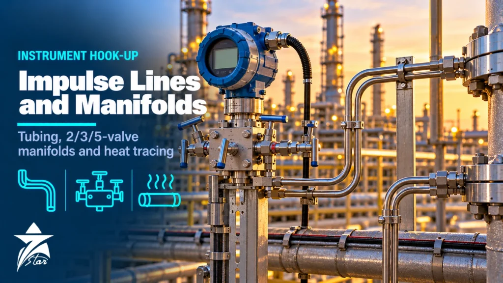
Instrument impulse lines connect a tapping point on a pipe or vessel to a pressure, differential pressure (DP) or level transmitter. They look like the simplest part of a measurement, yet many readings that drift, jump or freeze come from the hook-up rather than the transmitter. Gas trapped in a liquid line, liquid collected in a gas line, a plugged tap, a leaking fitting or two DP legs at different temperatures all add errors that no calibration can remove. This guide covers the main design rules: where to place the taps, how to slope and route the lines, which tubing and fittings to use, how 2, 3 and 5-valve manifolds work, when to use seal pots and condensate pots, and how heat tracing and GCC conditions affect the design.
What a Good Hook-up Must Achieve
Every impulse line design aims for the same goals:
- Transmit the process pressure to the instrument without adding a variable error.
- Keep the line filled with a single phase: all liquid for liquid and steam service, all gas for gas service.
- Allow the instrument to be isolated, vented, drained, zeroed and removed safely.
- Avoid plugging, freezing, solidification and corrosion.
- Keep both legs of a DP measurement at the same temperature and fluid density.
- Be short, simple and supported, with the minimum number of joints.
Standards and practices such as API RP 551 (Process Measurement) and company hook-up drawings turn these goals into detailed rules, and transmitter manuals add requirements for each model.
Tap Location and Instrument Position
| Service | Tap position on horizontal pipe | Instrument position | Reason |
|---|---|---|---|
| Liquid | Side of the pipe, at or slightly below the centreline | Below the taps | Gas bubbles rise back to the process; sediment at the pipe bottom is avoided |
| Gas | Top or upper side of the pipe | Above the taps | Condensate drains back to the process instead of collecting in the line |
| Steam and condensing vapour | Side of the pipe | Below the taps, with lines filled with condensate | A stable liquid column protects the transmitter from high temperature |
| Slurries and dirty liquids | Side of the pipe, often with flushing connections | Below the taps or close-coupled | Reduce settling; allow rodding or flushing |
On vertical pipes, taps can be at any point around the circumference, but the same rules on instrument position apply. For DP flow measurement with orifice plates, the two taps must also be at the positions defined by the standard; see our orifice plate flow measurement guide.
When the instrument cannot be placed where the rules require, for example a liquid transmitter that must sit above the taps, add vent points at all high spots and drain points at all low spots, and expect more maintenance.
Slope and Routing
The single most important routing rule is continuous slope. API RP 551 recommends a slope of about 1:12 to 1:10, and transmitter manufacturers such as Yokogawa recommend at least 1:10 even on runs that look horizontal. The slope direction follows the service: down to the instrument for liquid and steam, up to the instrument for gas.
Other routing rules:
- Keep lines as short as practical; consider close-coupled or direct-mount installation.
- Avoid loops, pockets and unnecessary high or low points.
- Run both legs of a DP measurement together, side by side, so they see the same ambient temperature.
- Keep lines away from hot equipment, exhaust outlets and steam lines that could heat one leg.
- Use bends instead of fittings where possible to reduce leak points; respect the tube’s minimum bend radius.
- Support tubing at regular intervals and protect it from foot traffic and mechanical damage.
- Provide enough room at the transmitter for manifold operation, venting and removal.
Tubing and Fittings
Impulse lines are usually seamless stainless steel tubing, commonly 316 grade, in sizes such as 1/2 in, 3/8 in or their metric equivalents of 12 mm and 10 mm. Larger bores resist plugging and reduce the effect of small gas bubbles; smaller bores respond faster on clean gas. Material must match the process: higher alloys such as duplex stainless, 6Mo or nickel alloys are used for chlorides, sour service or seawater environments, and tubing exposed to coastal GCC air benefits from corrosion-resistant grades.
Key points for fittings:
- Use one manufacturer’s compression fittings consistently, with matching ferrules and nuts. Mixing parts from different manufacturers is a common source of leaks.
- Match tube wall thickness and hardness to the fitting manufacturer’s tables for the design pressure.
- Cut tubes square, deburr, and insert fully before tightening; use gap inspection gauges where supplied.
- Keep the number of joints low and make all joints accessible for leak testing.
- Root valves at the process tap are usually piping class valves designed to the pipe specification, followed by instrument valves and tubing.
Tubing, fittings and instrument valves are covered in the pipes and fittings and fittings and valves categories.
2-Valve, 3-Valve and 5-Valve Manifolds
Manifolds combine the instrument valves into one compact block bolted or screwed to the transmitter.
- 2-valve manifold: one isolation (block) valve and one vent or test valve. Used on gauge and absolute pressure transmitters and pressure switches.
- 3-valve manifold: two isolation valves, one for each leg, and one equalizing valve between them. Standard for DP transmitters on flow and level.
- 5-valve manifold: two isolation valves, an equalizing arrangement and vent or test valves, allowing calibration checks and venting through the manifold. Some 5-valve designs use two equalizing valves with a vent between them, common in natural gas metering so that the equalizing path can be checked for leaks.
Manifolds are available in direct-mount, remote-mount and flanged-to-process styles. Direct-mount types reduce tubing and joints at the transmitter.
A typical sequence for putting a DP transmitter on a 3-valve manifold into service, with the equalizing valve open and both isolation valves closed, is: open the high-pressure isolation valve, close the equalizing valve, then open the low-pressure isolation valve. To take it out of service, reverse the steps. The aim is never to apply full static pressure to one side of the sensor alone. Always follow the transmitter and manifold manufacturer’s procedure for your model.
Seal Pots, Condensate Pots and Remote Seals
Condensate pots on steam and condensing vapour service provide a reservoir at the top of each leg so the liquid column height stays constant. Both pots must be mounted at the same elevation, and both legs filled with condensate before the transmitter is placed in service.
Seal pots contain a separating liquid that keeps the process fluid away from the transmitter. They are used for corrosive, viscous or solidifying process fluids, but the seal liquid must not mix with the process and the level in both pots must be maintained.
Diaphragm remote seals avoid impulse lines entirely by using capillaries filled with a stable fill fluid. They suit sanitary, corrosive, high-temperature and plugging services. Our pressure transmitter selection guide explains the trade-offs of remote seals in more detail.
Heat Tracing, Insulation and Sun
Tracing keeps the impulse line fluid above its freezing, pour or hydrate point. Options include steam tracing, self-regulating electric cable and heated enclosures for the transmitter. Rules that apply to any tracing:
- Trace both legs of a DP measurement equally and insulate them together.
- Avoid overheating; boiling the liquid in a liquid-filled leg creates vapour and a large error.
- Check the transmitter’s maximum process and ambient temperature where tracing approaches the body.
In GCC plants, cold is rarely the problem but sun is. One leg of a DP measurement in direct sunlight and the other in shade can differ in temperature by many degrees, changing the liquid density and the reading. Shades, insulation or routing both legs together reduce the effect. Lines carrying wet gas, heavy oil, wax-rich crude or sulfur still need tracing.
Common Problems With Instrument Impulse Lines
- Gas pocket in a liquid line: reading offsets or drifts; vent the high points and correct the slope.
- Liquid in a gas line: offset that changes with ambient temperature; drain low points, move the transmitter above the taps.
- Plugged tap or line: reading frozen or very slow; blow down or rod out, review line size and purge options.
- Leaking fitting or manifold: error on one leg, especially visible on low-range DP; leak test and re-make the joint.
- Equalizing valve passing: reduced DP and low flow reading; test and repair or replace the manifold.
- Unequal leg temperatures: reading changes through the day; shade, insulate or re-route the legs together.
Instrument Impulse Lines Hook-up Checklist
- Service type identified: liquid, gas, steam or slurry
- Tap positions and orientation per hook-up drawing and measurement standard
- Instrument position relative to taps correct for the service
- Continuous slope of about 1:12 to 1:10 in the correct direction
- Tubing material, size and wall thickness suitable for pressure and corrosion
- Single fitting manufacturer, joints made to procedure, leak tested
- Correct manifold type: 2-valve, 3-valve or 5-valve
- Condensate or seal pots at equal elevation and filled before start-up
- Vents and drains at all unavoidable high and low points
- Tracing, insulation and sun shading applied equally to both legs
- Tubing supported, protected and accessible for maintenance
Instrument Fittings and Valves We Supply
These products cover the connections, valves and filters used in impulse line hook-ups.
| Product | Type | Where it fits |
|---|---|---|
| Swagelok Tube Fittings | Tube fittings | Leak-tight connections on instrument tubing. |
| Swagelok SS-1RS4 Integral Bonnet Needle Valve | Needle valve | Root and isolation valves on impulse lines. |
| ABB Orifice carrier assembly with integral manifold FPD175 | Orifice carrier with integral manifold | Close-coupled DP flow installations. |
| Swagelok SS-DLS4 DL Series Diaphragm-Sealed Valve | Diaphragm-sealed valve | Isolation where stem packing leaks are not acceptable. |
| Swagelok SS-4TF-7 Tee-Type Filter, 7 Micron | Tee-type filter | Protecting instruments from particles. |
| Swagelok SS-810-61 Bulkhead Union, 1/2 in. Tube OD | Bulkhead union | Tubing passing through panels and enclosures. |
Send the tube size, material, pressure rating and quantity through our quote request form.
Sourcing Impulse Line Components Through Seven Star LLC
Seven Star LLC supplies instrument tubing, compression fittings, instrument valves, 2, 3 and 5-valve manifolds, condensate and seal pots and transmitter mounting brackets on request, together with transmitters from the pressure instrumentation range. Manufacturers such as Swagelok, Parker, Hy-Lok and Emerson are common in hook-up packages. We help with selection and cross-checking part numbers against hook-up drawings and bills of material; availability and lead time are confirmed at quotation.
Send us your hook-up drawing, bill of material or the part numbers of your existing tubing, fittings and manifolds, and we will prepare a quotation for the impulse line components you need.
Frequently asked questions
What are instrument impulse lines?
Impulse lines, also called sensing or gauge lines, are the small-bore tubes or pipes that carry process pressure from a tapping point on the pipe or vessel to a pressure, differential pressure or level instrument. Their layout decides whether the instrument sees the true process pressure or an error caused by trapped gas, liquid or blockage.
What slope should impulse lines have?
Impulse lines should slope continuously, without high or low pockets. API RP 551 recommends a slope of about 1:12 to 1:10, and several transmitter manufacturers recommend at least 1:10. For liquid and steam the line slopes down to the instrument; for gas it slopes up to the instrument so condensate drains back to the process.
What is the difference between 2, 3 and 5-valve manifolds?
A 2-valve manifold has one isolation valve and one vent or test valve and is used on gauge and absolute pressure instruments. A 3-valve manifold has two isolation valves and an equalizing valve for differential pressure transmitters. A 5-valve manifold adds two vent or test valves, or an extra equalizing valve with a vent, so the transmitter can be checked and vented without disconnecting tubing.
Why should impulse lines be as short as possible?
Short lines reduce the chance of plugging, freezing, trapped gas or liquid, temperature differences between the two legs of a DP measurement, and slow response. Where the process allows, close-coupled or direct-mount transmitters on an integral manifold are preferred.
When are seal pots or condensate pots needed?
Condensate pots are used on steam and condensing vapour DP measurement to hold a stable liquid column at the same height in both legs. Seal pots with a fill fluid separate the instrument from corrosive, viscous or solidifying process fluids. Diaphragm remote seals are an alternative where the process should not enter the impulse lines at all.
Do impulse lines need heat tracing in the GCC?
Freezing is rare in most GCC locations, but tracing is still needed where fluids are viscous or can solidify, such as heavy oil, wax-rich crude, sulfur or some chemicals, and for wet gas lines where hydrates or condensation form. Strong sunshine can also heat one leg of a DP measurement more than the other, so shading and insulation are used to keep both legs at the same temperature.
Was this guide helpful?One click helps us write better guides for engineers.
Thank you! Glad it helped. Need this equipment for your project? Request a quotation
Thank you. We will use this to improve the guide.